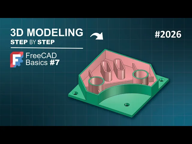
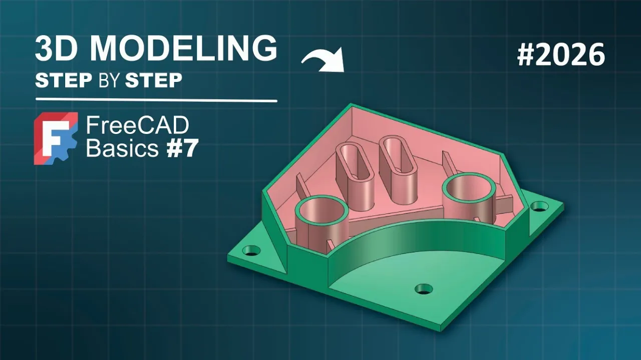
Here in FreeCAD is free to view. We have a free 3D model that we can consider a random free 3D model. It is made of simple shapes, but we can use it to get an idea of how some FreeCAD tools work for free 3D modeling.
This bolt was designed using a part design and sketcher workbench. In the next few moments, we will see the step-by-step process of its creation. The dimensions you see here were created using the draft workbench.
The advantage of this free 3D model shape is that it allows us to reduce the number of steps. Basically, you only need to create one half of it and then apply a mirror operation complete a part. In my view, this way of modeling is very effective as it greatly reduce modeling time.
Let's start with an empty file. Click on empty file option to create an empty document. Let's add a body object to the document.
Go to part design helper features and click on new body icon. Now, let's create a sketch attached it to the XY plane of the created body object. Go to part design helper features and click on new sketch and select XY plane as the attachment plane.
In the sketcher workbench, let's go to sketcher geometries toolbar and expand rectangle tools and select centered rectangle. Click on the region point and create a rectangle with these dimensions, 55 mm by 55 mm. Enter.
Escape the tool. And now, these two lines here, we are going to convert them into construction lines. By doing this, we are actually telling FreeCAD to exclude these lines from the solid that will be created from the sketch.
So, with these two lines selected, go to sketcher geometries and click on this icon to change the lines to construction lines. To close this geometry, we have to create a line between these two points here. To do that, we can go to the sketcher geometries and select the line command and start the geometry on this point and and here we have a closed geometry.
Now, let's escape this tool, right click, and let's close the sketch also. Select the sketch in the tree view and click on pad tool and go to the task panel. In the pad parameters, change the length to 2 mm.
This is the real length of this extrusion. And then click off and the extrusion will be updated. Press okay to finish the pad parameters.
Next, we will create a sketch on this face here. And to do that, what we have to do is to select this face and then go to part design helper features and click on new sketch icon. In this second sketch, the first thing that we'll do is to import the edges of the free 3D model into our sketch as reference geometries.
To do that, we can start by going to the sketcher geometries toolbar and click on this icon, toggle construction geometry. And now, we go to sketcher tools toolbar and we click on external projection tool. Now, we click on this face and here we have these lines.
If you go to the tree view and hide the pad feature, press this icon. As you can see, here we have these three lines here as construction geometries, as reference geometries. Escape the tool and let's change back to normal geometries and now let's select arc tool.
Click on this vertex and create a base arc. Next, let's select the polyline tool and zoom in here. Let's start by clicking on this point and press M two times to create a base line, a normal line.
And now, click on this imported edge, order edge, and create a horizontal line. And now, let's close this geometry. Click on this end point and now escape the tool.
Go to sketcher constraints and select dimension tool. Click on this arc, click off, and set 29 mm for the radius of this arc. Now, go to this point here.
Click on it and now click on this point and let's create a horizontal distance of 15. 5 mm. Let's do the same for this point and this one.
The same distance, 15. 5 mm. As you can see, here we have a fully constrained geometry.
And the sketch is fully constrained as you can see. But now, what we are going to do is to create an offset of this geometry. And to do that, we can start by hiding these all dimensions, these all constraints.
Just go to the task panel, go to constraints and click on this eye icon. Escape the tool and now click on this line here two times to select this geometry. Next, go to sketcher tools toolbar and click on this icon, offset icon.
On the offset parameters here on the task panel, check this option, add offset constraint. I will check this option and then I will set minus 1 mm for the offset and here we have another closed geometry. But here in the sketch edit parameters, as you can see, we have five degrees of freedom.
This happens because these construction lines here, as you can see, they are not constrained. As you can see, I can move this line here. So, this is the reason why we have five degrees of freedom here.
We have five construction lines as you can see. Okay, now, let's select a base line and this one here and let's convert them into construction lines. Click on this icon.
And next, select the polyline command in the sketcher geometries toolbar. Zoom in here and let's close this geometry. Click on this point here and let's create a horizontal line.
Click on this line here. And now, click on this point and escape the tool. But we have a problem here.
We have to fix this point on this one here. To do that, it's very easy. We can select this point and then this one here and go to sketcher constraints and use this command here, coincident constraint.
And as you can see, it's not working. To fix this, we can use a horizontal constraint to fix this point on this one here. So, the first thing that we have to do is to undo this step here.
Click on this icon and then select these two points again and now go to sketcher constraints, expand these tools, and select horizontal constraint. And here we have this. Now, let's go to this side and let's select arc tool.
Click on this. Click on this point. We will use this point as the center point of this arc.
And now, just click on this point and click on this line here. As you can see, the arc is fully constrained. Now, let's use the line tool to close this geometry.
Create a line here between these two points and escape the tool. And here we have this. What is missing to do now is to create a slot here on this location and a cycle geometry here on this location.
So, we can start by going to the sketcher geometries and select slot tool and create a slot here with with a length of 10 mm and the angle is not important. Next, we can set the radius of this slot, which is 3 mm. And then, we can escape the tool and now, we will make this line here.
Select this line here of the slot geometry and this construction line and let's make them parallel. Go to sketcher geometries and select cycle command and let's create a cycle here with a diameter of 12 mm and escape the tool. And now, let's use the dimension tool to fix these two geometries.
Let's start by clicking on the center point of this slot and then on this end point. Let's create a horizontal distance of 16 mm. And now, from this center point to this construction line, the distance we can set 5 mm as we can see on the free 3D view.
And now, from this center point to this end point, we can set 15. 5 mm. From the center point of this cycle to this end point here, we can create a vertical distance of 15.
5 mm. Let's escape this tool and let's create an offset of this geometry. Double click on this line and as you can see, here we have the selection.
Next, go to sketcher tools toolbar and click on offset command. And I'll check this option and set minus 1 mm for this offset and enter. And now, close the sketch.
Pad command icon. And set 8 mm for this extrusion and then press okay. The next thing to do is to create another sketch and we're going to use that sketch to create an extrusion.
So, select this face for example and click on new sketch. In this sketch, we can use the slot tool to create the geometries that we need. Select slot command.
And then, let's create a base slot here with 0. 5 mm. Let's create another.
Click on the origin point and click off. Let's say 0. 5 mm for the radius and enter.
Now skip the tool. What is missing to do is to set the placement of these two geometries. To do that, we can start by importing some edges of these freedom model into our sketch as reference geometries.
Click on this icon. This icon external projection. And now click on this face here.
Now let's hide this freedom model. Go to the tree view and click on this icon. Now here, skip the tool and the first thing that we can do here is to center the center point of this slot on this line here.
Let's go to sketcher constraints and use this tool here. Click on this point. Now this point and now this center point and as you can see we have this.
Next, let's select the dimension tool and click on this line here and now on this center point. And the idea here is to set the distance of 0. 5 mm the radius of this slot geometry.
The next thing to do is to make a base line here parallel to this imported edge. Skip this tool. Select this line and now this line and go to sketcher constraints and click on this icon here parallel constraint.
Two degrees of freedom now, what we can do is to zoom in here and bring this center point to this location and then select this point and now this imported edge and let's place a constant constraint and here we have this. Now let's go to this center point. Let's move this center point of this slot to this location and now what we can do here is to select this point and then this imported arc and place the same constraint and here we have this.
Let's close the sketch. And the next let's use the pad tool to extrude this sketch. Let's add 4 mm for this extrusion and then press okay.
Next, let's create a sketch on this face again. Select this face and click on new sketch. Let's use the external projection command to import this line here as a reference geometry into our sketch.
Next, let's change the geometries to normal mode and let's select cycle command and let's create a cycle here on this imported edge 4 mm and let's create another cycle with the same dimension. Skip the tool. As you can see we have three degrees of freedom.
The first thing that we can do is to constrain the placement of these of these cycle in the X direction. Select dimension tool. Click on this center point and now on this end point and let's create a horizontal distance of 10.
25 mm. Toggle construction geometries and external projection and now click on this vertex and here we have it in our sketch as a reference geometry. And now select dimension tool.
Click on this center point and now on this point and let's say 4 mm and now from this center point to this point, let's create a vertical distance of 4 mm. Close the sketch and now let's use the pocket tool to remove material. Press okay and here we have the holes.
What is missing to do here before we mirror this model is to create a hole on this cylinder here. To use the hole tool, we have to select this face for example or we can select the base edge and then click on the whole feature command icon. As you can see here we have the preview of the hole.
The first thing that we can change in the whole parameters is the depth of this hole. So let's go to the whole parameters here on the task panel. Go to the depth parameter and change it to 8 mm.
Click off. As you can see we have this. If we change to front view, as you can see we have a drill angle here for this hole.
We can remove this. We just need to go to the whole parameters and uncheck this option, the drill angle option. And now press home on the keyboard and the next thing to change is the diameter of this hole.
10 mm and then press okay and here we have the hole. Let's go to the tree view and click on this pad feature and now hold the shift key and and click on the whole feature and as you can see we selected these all features. Now let's go to part sign transformation features and click on mirror.
This is the preview and here we have to fix the plane of this mirror feature. We click on it and then we click on this last option, select reference and now let's rotate the view zoom in here and select this face. And as you can see we have this.
Let's press okay to finish this. This is the final shape of the model. Thank you for watching this video.
If you find this video useful, please don't forget to hit like and share this video with your friends.