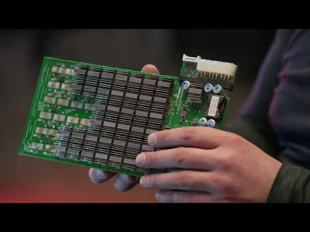
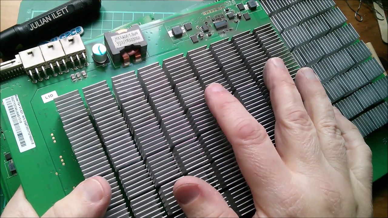
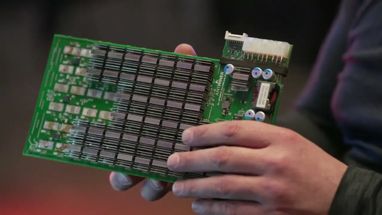
okay in this lesson we're going to go ahead and cover hashboard Diagnostics so we already went ahead and covered the main components the different circuits on the board as well as the way the signal flows with that kind of knowledge we can then go ahead and move on to hashboard diagnostic so that way we can figure out exactly what's going wrong with the board [Music] when we are doing diagnostic on a hash board we want to do the same thing with consolidation we want to do a complete visual inspection so we're looking at the board
we're seeing if anything is missing damaged off as you can see here these heat sinks are crooked so we probably don't want to plug this in without removing these heat sinks and seeing what's going on underneath there that Asic ended up shifting and cause a short circuit and end up frying out your board again you want to make sure you understand signal flow as well all the main circuits so once you completed that module we can go ahead and get started doing diagnostic so to do diagnostic we're going to need a few things so you're
going to need one of the tools you're going to need is a variable power supply uh five amps might cut it for some of the older models for the newer models you're going to want 10 20 amps and some of the even newer ones require even more than that so I'd say a 20 amps a good place to start it's also good to have multiple variables so that way you can also not only use it to power the board but also use it to inject voltage into the board itself on a different circuits another thing
we're going to need is a test fixture or a test jig this is a third-party one I like to call it the tie tester there's lots of them out there on the market and we have them available so if there's anything you need let us know this basically plugs into the hash board to run tests so that way you can put voltage through the hash board another thing you're going to need is a multimeter I recommend a fluke 15b Plus that way we can make a little more standardized in the industry we all get the
same somewhat the same readings also having some needle tips will help substantially because that way you can actually if you take a look you can go in between the heat sinks with it I want to be careful that we're not accidentally touching the ground at the same time because then you're going to short out that signal so this first one here with the wave is going to be voltage on alternating current so we don't want to use this for DC the next one is DC voltage now we don't want to use and test alternating current
with this because then it can fry your multimeter so you want to make sure you're selecting the right one for the kind of current you're you're testing most the time we'll be using just the DC voltage and this will help you test the voltage between two points we can also come here top dead center is going to be resistance we can use this to test components in circuit and try to see what the resistance is now you can use this to test the resistor and try to get the value of it but just remember Ohm's
law if you have resistors in parallel or in series it will give you a different reading from there we have press the button once and we have this little beep I call it the beep mode basically it's continuity mode so it tests to see if two points are connected together in circuit it'll beep at you if you're doing like ground to ground for example or if those traces touch each other and last but not least we also use diode resistance we use this mode to test the A6 themselves we put the red lead on the
ground of the heatsink like so and then we take the black lead and we use that for the test point this will give us what's called diode resistance it's actually more testing for voltage drop between two points so this will tell us if the Asic itself is heated properly or maybe the A6 are missing components so that's why we're always doing a visual inspection but ideally if your reading is too high on diode resistance it's going to mean that you have an open circuit it's going to be as if that Asic itself is like not
even attached to the board now if you have a value that is too low that's going to tell you have most likely a short circuit so you have like a solder bridge where two of the leads are accidentally soldered together and that's something we definitely want to make sure we check before we even test the board so if this is a board that we pulled out and we already got to check the kernel log might give us a better example of what's going on with the board so let's say it says zero Asic we have
no idea what's going on same thing if we don't know what's going on you're going to have to probably plug it in so again we're always going to want to do that visual inspection make sure we don't see any fried components especially the Moss chips if those things look fried we don't want to plug it in but for zero Asic what we're going to do is we're going to plug it into a power supply and we're also going to plug it into the test jig and then we're going to see what it says and in
this case it's saying zero Asic so what do we do so first thing we do is we want to make sure that return signal is going from the last chip to the first chip right so we'll test the um in this case it's bit main amp minor so it's going to be Ro RI RX we'll just call it the return signal it's going to be the same for any maker model so that return signal let's say we don't get it here right well what powers The Last Ship it'd be the ldo so then we test
the ldo we don't got voltage on the ldo okay what powers the last few domains the Boost so we test the Boost we find out the Boost doesn't have voltage so then what powers that what turns that on and off well that would be the Moss chip so are we getting voltage after the Moss or are we not well let's say we're not getting voltage at the Moss well then we want to see if our pick chips even enabling that Moss to open up so in that case then let's say we come over here and
test here and find out we have no voltage coming in and find out that we didn't even turn on the power supply uh so that's kind of you just want to follow that signal through the board and see exactly where it breaks again if we're back at The Last Ship and we have voltage you could go one chip after another until you finally get to the first chip to see where that breaks usually what I like to do though is is that if you have voltage here I'll just jump halfway to the board see if
there's voltage here and then just keep going let's say no voltage here but there is here then you just kind of connect it together and find exactly where that voltage stops or breaks might be a low voltage that kind of thing so once we get that return signal fixed that will bring us into what's called some Asic so with some Asic it will say like you know one Asic 10 Asic you know there's 63 A6 here let's say it says 62 Asic anytime it gives us a reading other than zero that's what will be called
as some Asic in that case that usually means the return signal is likely good not always but just enough that it's letting the signal get back to the control board or the test jig to let us know that it's some Asic so let's say it's 10 Asic right so first thing we want to do maybe we got that from the kernel log or we just plugged it into the test jig and found out that there's only 10 A6 being found first thing we want to do is is take our multimeter and we want to set
it to diode mode and in diode mode we want to test not only chip number 10 but we want to do the chip before and the chip after so we're going to test chip what would that be chip 9 10 and 11. and we do that for all five test points or all the test points there's usually five seven give or take test points for each Asic so we're going to do the diode resistance on that and make sure it's in range if in doubt you can always go over a few domains to an identical
one or an identical chip and see if you get the same reading or you can take another board that you know works and test it and compare now we test this and the diode resistance is out of range first thing we want to do is we want to rework that chip to make sure it's back in range before we plug it back in the reason for this is let's say there's a short circuit there and you plug it in now you just fried the maybe the component or even worse you just fried traces and thus
causing a dead board so we want to make sure that we're always always always testing diode resistance before and after we ever rework a chip so once we get it back to range we then can go ahead and plug it back in hopefully by that time we fix the issue and we have all the Asics found if not we just kind of keep going and trying to make sure that signal finally makes it to the last jump so again zero Asic we want to make sure that return signal is going Last Ship to first chip
some Asic we want to make sure all the other signals go from first chip to last chip then you have some other issues that you might come across that would be like maybe a pick air eprom info air temperature sensor air stuff like that and so first step would definitely be you can always try flashing the pick you can try flashing the eeprom temp sensors you can do a visual inspection you can try replacing the temperature sensor can also be the Asics that are attached in series with the temperature sensor so it might not even
be the temperature sensor circuit itself it could be the Asic after in in series in this case it would be the chip before it because the return signal goes from last trip to first chip that's kind of the basics of how we do diagnostic just best to have another board to compare to so that way if you have a working board you can test all the different test points and see exactly what kind of reading you should get ready Freddy all right two seconds oh just because you I was set for that exposure not ready
all right so in this module we're going to go ahead and cover rework Basics we're going to go ahead and actually do some rework today so what I like to do is basically rework the main components in each main circuit so what we're going to start off with is the Moss chips so let's go ahead and take them off and put them back on for good practice from there we're going to want to do the Boost so we want to do all the components in the Boost from Big component all the way down to the
smallest component that we usually work on the Boost itself usually has you know uh big and small so I like to do that so that way it makes great practice there is one size smaller that we work on o402 is the smallest in the Boost 0201 you can see on like 17 series once we get all the components taken off and put back on the Boost I definitely recommend doing one component at a time and not just take them all off and try to figure out which one goes where after that we're going to want
to go ahead and do some ldos we want to do the Clock Crystal oscillator we want to do the pick eprom if it has it we want to do just basically all the main components that way we can get familiar with how to rework them so let's go ahead and get started on the Moss so here is a moss chip for this we're going to need a heat gun we're also going to need some flux and we're also going to need some tweezers so for the tweezers it's all preference I usually like the long and
skinny ones I can go under the light for me yes there thank you appreciate it so I like to use the small thin long ones some people they use other ones like the angled so it's really all preference every Tech is different so when we're reworking a component we don't want to grab it by the feet this direction so if need be let's go ahead and turn the board a complete 90 degrees so that way when you come in you're grabbing it this way so really depends on your comfortability some techs like to come in
forwards like this other texts like to come in from the side I'm more of a a lobster than a crab so can you focus on the uh oh yeah I think it's pretty focused can we help it's harder to tell and it's when you have the smaller previews is that better there's the shark you stop there that's a shotgun okay it's you know shallow depth of field it's always going to be a little softer uh it's it's soft you did you bumped it it's very delicate like you know you step there we go okay is
that better can I adjust it yeah where's the focus adjustment yeah I literally get paid to do this he's really good at it I get paid to pull focus on set as what I'm saying it's kind of a big deal I mean if it's not sharp what's the whole point of doing it right there is as sharp as it will get okay go ahead all right so when we're reworking these components uh what I like to explain is is that this solder is a metal so what you're doing is you're literally melting metal into a
liquid this is a very important concept to understand reason being is is that you need to make sure all of the solder is melted into a liquid at that point in time it'll just come off really easy like butter now we don't want to squeeze on the chip too hard and start chipping the chip very easy to do as you can see another thing we want to avoid is is scratching the PCB board that's also very easy to do so you want to think of it kind of like your skin so you don't want to
take your tweezers on your skin and scratch yourself so same kind of idea you don't want to scratch the board as you can see the copper just got exposed we want to cover up any exposed copper because that will corrode over time so you can use like a solder mask let's go ahead and do the reworking so first thing we're going to need is some flux so go ahead and add some flux I like to put it on just the feet of the board is all you need a little bit will do you now also
depending on the board the temperature of your heat gun will also determine that so if you have a board that has a low temp solder it's going to be a lower temperature and like the newer generation models you're going to need higher temp for the higher temp solder another thing is is sometimes there's a heat sink on the back where the Moss are so let's go ahead and remove that first otherwise it'll be very difficult to remove the Moss actually otherwise yeah we're not really using the microscope for this this will be more for like
just showing from the camera angle okay all right so let's go ahead and set the temperature of the heat gun when you're removing heat sinks you can set it a little higher on the s9s I like to do around 400 degrees oops press the wrong button now it's better to start at a lower temperature and kind of raise your way up we don't want to burn the board it's very easy to burn the board so if you put too much temperature in the board you can stress it out that's why you can kind of start
at a lower temp raise it up a little bit raise it up a little bit and then maybe the solder will melt so you can go ahead and put the heat gun directly on the heat sink I also like to take my tweezers and give it a little wiggle because we don't want to overheat it especially if you're doing like the Asic chip and as you can see when it's ready it just comes right off you don't want to force it two seconds two seconds I was putting active stabilization now all right so we also
probably want to remove this plastic or rubber whatever you want to call this foam so we don't want to melt it heatsink the Xbox 360. so there we have it get this back in focus there we go it's done with the heat gun you can literally go on top of the component without touching it it's not a problem ideally we want to get the heat into the board as well as the component so you can do circles if you want some people like to bless their you know work so you can give it a nice
little cross now what we're looking for is is that solder to look nice and shiny when it's ready it will be ready we don't want to just force it up when it's not ready as you can see not ready and after about a minute or so and you're still not getting the results you want you can always increase the temperature or increase the airflow I like to have my air speed a little high only thing is if you accidentally bump some of the smaller components they'll just go flying [Music] so if you're a person that
likes to have your heat gun a little further from the component you might need to increase the air speed and the Heat it's also good to have it as top dead center as possible you don't want to have it kind of at an angle [Music] as you can see it's getting ready so I like to roll it up and roll it back down so you roll it up get it set properly once you set properly there we go you want to get it set properly and then so again you want to roll it up and
then roll it back down so you get it right into place and then you can roll it you don't want to shift it around too much because then you can cause those pads to lose its solder you can also push straight down on the chip to help make sure you have good contact you want to make sure it's fully melted you don't want to do a pseudo solder that's basically where the solder is a cold solder joint and it's not really attached so you want to go ahead and do all of the Moss chips during
this module so we can get the best practice to clarify you're taking Moss chips on and off just to practice but not actually replacing right correct more so like the tutorial showing how to take them off shoot do you think we should say that or um so I mean you're still doing the same thing you're doing if you would do a repair and all right yeah I think it's fine okay it's still the same task uh two seconds I'm just getting better support oh my God that's so much easier to hold okay go ahead okay
so you want to utilize that heat that's already in the board to get the rest of them done be a lot faster so we're just basically just taking the components off and putting them right back on for good practice I'm at 150 millimeters yeah I'm acting on the active and then a steady shot standard you can always give it a small little love Taps if it shifts too much you might have to re-pick it up and put it back down you just want it as completely Center as possible you can see it dry right on
camera that's the Moss once we've gotten pretty good at that and we're an expert we can now work on the Boost so that's the entire boost we want to go ahead and remove all the components and put them back on me I like to take off this inductor first it's going to absorb most of the Heat there we go now we can start with all the bigger components if we want be a lot easier for us take them off put them back on as you can see it's really easy to knock components while you're working
so be very careful especially on the smaller components see now just blows away and you won't know where it went be lucky to find it and it's gone so again there's a conformal coating on here so what I like to do is add just a little heat enough to melt the plastic or the conformal coating but not enough to actually melt the solder and just kind of scrape away at it slowly but surely you can always bring the heat gun in a little bit bring it back out bring it in bring it out again we're
not trying to melt the solder we're just trying to melt the conformal coating yeah I was gonna say it's a little softer then you can use a Q-tip with some 99 isopropyl alcohol to help clean so you want to take them off and put them right back on for these smaller components I usually like to do hot soldering as you can see the pads are melted and I'm just placing it right in place now I can remove the Heat let it solidify and remove then you can use another type of flux it's a mildly activated
rosin flux I will say it was just one stop underexposed you're definitely fine then you can just add a little dab will do ya re-bring in the heat and then it'll actually kind of set itself sometimes you might need to agitate it just a little bit is that brown stuff something you really should worry about or talk about uh I did already so as you can see one side has white side and the other side has a black side it'll still work upside down there we go now this step up I see you want to
make sure when you do it you place it back exactly how it was it does have a Direction and this is one of the most important components on this if you accidentally don't set this properly it will fry your board out same thing if you place this diode on backwards you can fry out your board but again we're just going through and we're just placing all the components back after removing them again I recommend doing one at a time [Music] now we're always cleaning up after ourselves see and that's what a pseudo solder is it's
not completely attached although you thought it was it stays hot for quite a long time as you can see the solders are still melted once it's on there it'll be on there and also look on the bottom side of the chip to make sure everything looks good looks pretty dirty so we can go ahead and clean it fluxes your friend so this is what would be called cold soldering as you can see the pads are still solid hot soldering is where we would melt the pads first all right let me see the capacitor kind of
sucked itself into place you can also do the pick up yeah so you want to make sure that as you can see this circle aligns with this other circle on the board so we want to make sure that we're placing it back correctly the one thing always goes surprised you know that but yeah the uh this little dot here also represents that this is pin number one there we have it so if you better wrap up on camera three and say something hey that's the basics of rework now again be very careful as this will
continue to be hot we don't want to burn ourselves so we'll stay hot for a long period of time that wraps up this lesson so go ahead and do your practice do the Moss to the Boost circuit do some of the other components on the board just get familiar with all the different components that we're going to be working with taking them off putting them back on might be a little frustrating at first but with some practice you'll finally get there and with some of these techniques that we taught you it'll make things a lot
easier so yeah go ahead and if you haven't already started go ahead and start reworking all the components [Music]