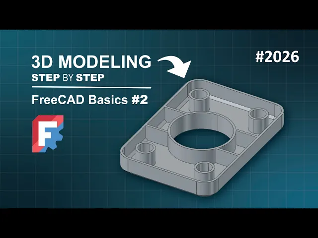
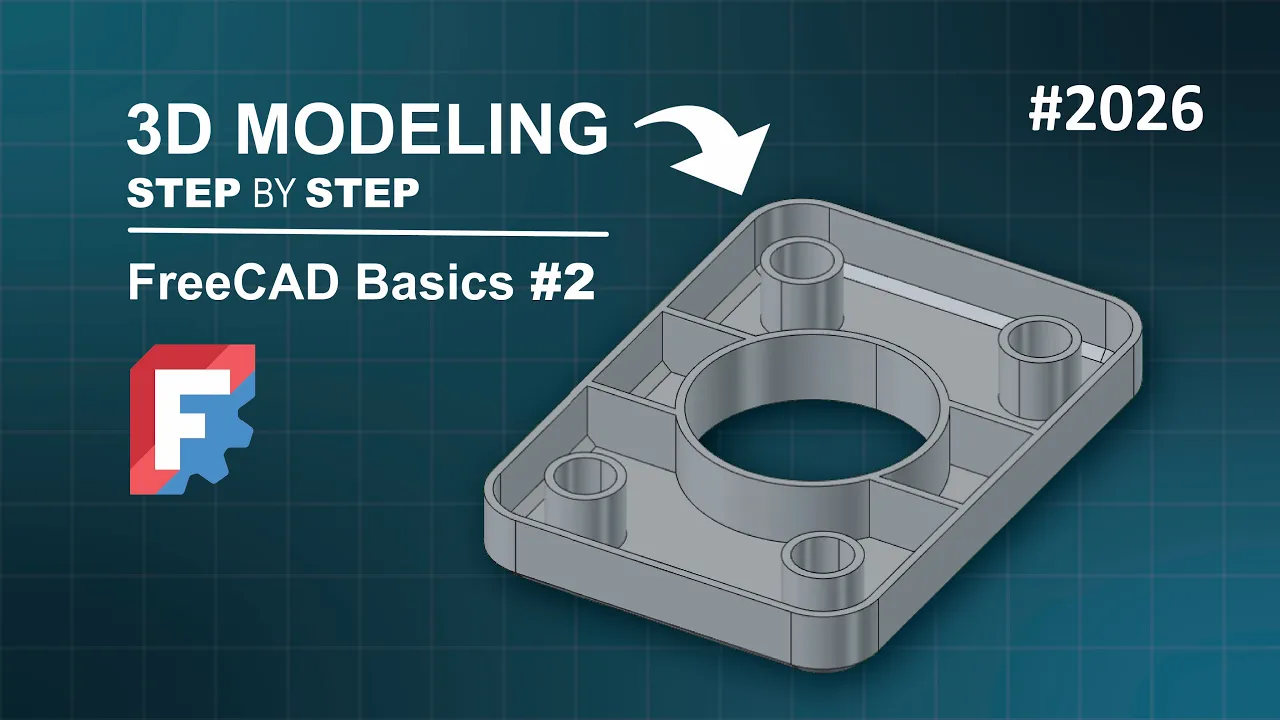
In this video, we will once again model a free the object in FreeCAD using the main freedom modeling workbench. For this video, we will use this free the model, which can be created in under 6 minutes by a more experienced user. This is a straight to the point video, so I recommend that you already understand what the commands in the part design workbench do.
To start, let's create a document using the empty file option available in the new file area on the start page. Let's add a body object. Now that we have the body object, we can start modeling.
But first, let's look at the geometry of the free the model and plan the commands we will need. From a top view, we can notice that most of the features are symmetrical. We basically just need to create the base solid, apply a chamfer on the bottom, add thickness, create a sketch with these geometries, and extrude it, create holes, and finally apply a mirror.
In the FreeCAD part design workbench, this means working with the pad, chamfer, thickness, and mirror tools, and also using the sketcher workbench to create the sketch for the holes. Let's do it. Let's start with a sketch attached it to the top plane.
I mean the XY plane. Go to the part design helper features and click a new sketch command icon and select the XY plane as the attachment plane for this first sketch. With the sketcher workbench, as you can see, here we have the sketcher geometry tools, and here we have the sketcher constraints that we can use to constrain the geometry and set the dimensions.
Go to the sketcher geometries and select rectangle. Start the geometry at the origin point and set set 100 mm for the width of this rectangle and 70 mm. Here I have the geometry constrained.
Skip the tool, right click, and as you can see the sketch is fully constrained. What is missing to do on the sketch is to add a fillet here on this corner. To do that, we go to these tools here, the sketcher tools.
Okay, let's select the fillet tool, and then click on this line and this vertical line, and here we have a fillet. As you can see, one degree of freedom here. Let's select the dimension tool and then click on this arc and click off, and now we can set the dimension of this arc, which is 20 mm, and then press okay.
And the sketch is fully constrained again. Now we can close it pressing this button. And now here on the 3D view, just press home on the keyboard to center your sketch on the 3D view.
As you can see here, we have the first sketch, and this sketch is attached to the XY plane. If you want to see the attachment plane, you can go to the sketch in the tree view, select it, and then go to its parameters, its properties, and you will see here in attachment support. Next, it's time to extrude the sketch here to create a solid.
To do that, we need to select the sketch on the tree view, and then click on the pad command icon of part and workbench, and here we have a preview of the solid with a falling off 10 mm. Extrusion mode is one-sided. No problem here.
We will leave this option as it is. The type is dimension. No problems here.
What I have to change here is the length of this extrusion, which must be 25 mm. Just set 25 mm, and then click off. As you can see, the length of this extrusion increased.
Also, we can use this arrow here to increase or decrease the length of the extrusion. If we drag this point here to this direction for example or this direction, as you can see the taper angle is increasing or decreasing, okay? Here we don't need to change here, only zero and okay.
Just press okay to finish the pad parameters task panel and here we have the free solid. The next thing to do is to create a chamfer here on the bottom. Select this edge and then click on chamfer command icon and then change its size to 5 mm and then press okay to finish it.
And the next step is to create the thickness on this solid here. To do that it's very very easy. Hold the control key and select the top face, this face and next to this face and then click on the thickness command icon.
And as you can see we have a preview here, 3 mm. Just click off and we'll have this. And then press okay to finish the thickness parameters.
The next thing to do is to create a sketch. In that sketch we'll create geometry that we'll use to create another solid. Click on the new sketch command icon, select the XY plane as the attachment plane for this sketch.
We can see the axis crossing. To fix this we go to this icon, we switch to the section video and now we can see. Let's start by selecting the circle command and create a circle here, 26 mm.
Enter. Two degrees of freedom as you can see. Let's use the dimension tool to fix the placement of this geometry.
Select dimension and now click on the center point of this circle. Click off and the distance must be 6 to 8 mm from the center point of this circle to the vertical axis. One degree of freedom, select this point, and now click off, set 43 mm for the vertical distance, and now the geometry is full constrained.
Let's go back to the full view, and let's import some edge of the 3D model into the sketch. To do that, let's first change the geometry to construction geometry because we need to import the geometry of the 3D model as construction geometries or reference geometries. So, click on this icon to change the geometry to construction geometries, click on external projection command icon, and next zoom in and click on this edge here, and go back to section view, and as you can see, now we have this line here.
Let's change back to normal geometries, and select the cycle tool, and then start a cycle in this point here, 86 mm, and next select the rectangle tool. Start a rectangle on this extracted edge, and create this rectangle. And create this, and next this rectangle.
Okay. Now, let's go to sketch tools, this toolbar, and select trim tool. Now, let's trim this arc here.
Let's remove this line, this line here, and next this arc, and this line here, and next this line, and this arc, and this line. Escape the tool, select these two geometries, these two geometries here, and next this geometry here, and press delete to delete it, and now we have six degrees of freedom, as you can see. Select this geometry and delete it.
As you can see, three degrees of freedom. Let's select dimension tool, and let's up by setting the length of this line here, which is 3 mm, and the placement of this geometry. Let's select these line and next the vertical axis and then create a horizontal distance.
The distance here must be 25 mm and then press enter and one degree of freedom as you can see. What is missing is to constrain these arc here. Let's select this arc and then this arc here and make them equal.
And the sketch is full constrained. Let's close the sketch. If we rotate the view, we can see that we have the sketch at the bottom.
This happens because we attached the sketch in the XY plane. To fix this, we can change the attachment of the sketch. Go to the tree view, select the sketch 001, go to its properties.
As you can see, we have the attachment support as origin XY plane. To change this, we go to map mode. We click here and then in these three dots.
On this task panel, we need to click in plane button. And so in and for example, select these top face here. We have thickness face eight here.
Okay? Next, we select the sketch 001 and we go to the pad command icon. And on the pad parameters, what we need to do is to change the type to up to face and then select these face here.
And then press okay and it's all for this step. Okay, the next thing that we have to do is to create two holes on these solid. To do that, let's start by selecting these edge and go to the whole command icon.
Increase the diameter to 20 mm and then click off. If we change to the front view, we can see Yes, it's better to increase the depth of these of these hole. Okay, like this and then okay.
And then press okay. And here I have the hole. Now, select this edge here and use the same command.
Now, I have to increase the diameter to 8 mm and then the depth to, let's say, 100 mm and then press okay. And here I have this. What is missing now is to create a mirror of this body object.
We don't need to mirror the features. Let's mirror the body object. So, select the body object and go to the mirror transform tool.
On the mirror transform parameters, let's go to transformations. As you can see here, we are transforming the body, not the shapes of the body object. Okay, let's go to transformations.
Right click and select this option. Add mirror transformation and then change the plane to, let's say, YZ plane. Now, we have this.
This is a preview. If you don't want to see this, you can go to preview here in that task panel. Check show final result and uncheck the show preview overlay and you will get this result.
Press okay here and let's mirror this object again. Right click and select mirror transformation. And now, this time, let's change the plane to XZ plane.
Go to plane and change it to XZ plane. And then, okay and okay. And this is the final model.
So, this is how we can use the Part Design workbench commands to model an object like this. In the next few minutes of this video, I will show you how a more experienced FreeCAD user would create this 3D model. Okay, I will start by creating a new document pressing Ctrl + N.
And I will save the document pressing Ctrl S. I will save as model 02. Um the first thing that I'm going to do is to create a sketch attached to the XY plane.
I will press S on the keyboard and select the XY plane. I will call the rectangle tool and start the geometry at the origin point and I will say 100 mm for the width and 70 mm for the height. And I have this.
Next, I will create a fillet here. I will press F and then select this line and this one here and call the dimension tool. I will constrain the radius to 20 mm and then I will close the sketch.
Next, I'll press home on the keyboard. I will select the sketch and press A to extrude the sketch and I will change its length to 25 mm and then I will press okay. I will rotate the view and then select this edge press C to create a chamfer.
I will change its size to 5 mm and then I will press okay. I will press home on the keyboard and next I will select the base top face. Hold the control key and select this face and this face here and I will press T on the keyboard to call the thickness command and I will set its size to 3 mm and then press enter and here I have this.
Next, I will zoom in here and I will select the base top face and create a sketch attached to this face. I will press S and the first thing I'm going to do on the sketcher workbench on this sketch is to call the cycle command and create a cycle here with a diameter of 26 mm and then I will call the dimension command pressing D and I will select the center of this cycle and create a horizontal distance of 6 to 8 mm and from the center point to the horizontal axis, I will a the vertical distance of 43 mm. I will hide these all constraints and call cycle command again and create a cycle with a diameter of 86 mm.
And next, I will call the rectangle tool. I will start the rectangle at the vertical axis and I will create another rectangle here like this. And next, I will create a base rectangle.
And now, I'm going to change the geometry to construction geometry by pressing space bar. And I will call the projection geometry command pressing E. And now, I will import this edge into the sketch.
Okay, next, I'm going to skip this tool and call the constraint constant pressing X on the keyboard and now I constrain this point to this imported edge. Next, I will call the trim tool pressing T on the keyboard and I will remove this arc, these two lines, and this line also. And the next, I'm going to remove this arc, this line here.
And next, this two this line, this arc, this line. And now, I skip the tool. I select these all geometries that I don't need and I hit delete.
And now, I have seven degrees of freedom as you can see. The first thing I'm going to do is to select this arc and this arc and make them equal pressing control equal on the keyboard. Six degrees of freedom.
Next, I'm going to call the dimension tool. I will start by setting the length of this line here to 6 2 3 mm and I will set the distance from this line to the vertical axis to 25 mm. Now, I'm going to check what is missing here by dragging these by dragging these lines here.
As you can see, I have this problem and this problem. I'm going to select these three points and then make them constant pressing X and as you can see, the sketch is fully constrained. I will close it.
And next, I will press E to extrude. I will change the type to after face and then select this face and next, I will press okay to finish the pad parameters. Now, I'm going to select this edge and create a hole.
I will increase the diameter to 20 mm and then I will drag this arrow and then press okay. And next, I will select this edge and create another hole. I will change the diameter to 8 mm and then drag the arrow and okay.
Now, I'm going to create a mirror transformation of this object and to do that, I'm going to select the body object and press MT on the keyboard and here I have this. The first thing I'm going to add is a mirror transformation in the YZ plane. I will go to transformations in the task panel, right click and this option.
Change the plane to YZ plane. And okay. Right click again, mirror transformation.
This time will be the XZ plane. And I'll okay and this is the final model. I will save the document pressing control S.
During the modeling process, you might have noticed that most of the time I was using shortcuts. Yes. That is something experienced users do.
If you are interested in speed while modeling, know that you can set shortcuts for commands in FreeCAD. FreeCAD allows you to do it. Thank you for watching this video and see you in the next one.