hello and welcome to my next tutorial prepo mix this time i'll show you how to connect a edge of a shell part to surface of a solid part let's import the geometry first and create a new model and meanwhile i will tell you what's the purpose of such modeling approach and this is quite commonly used when we model a component that can be treated as shell but it has a region that we need to model more accurately we need more accurate results in specific area and solid elements are necessary in particular region as you can
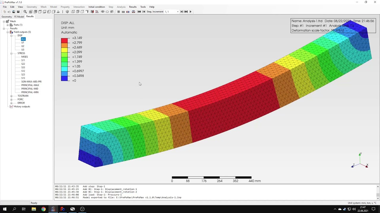
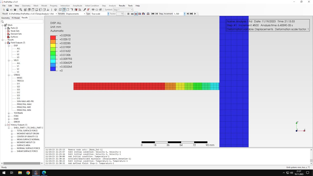
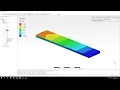
see we have a simple example of a beam uh this will be cantilever beam fixed at this end and we have a solid part right here and there's also a shell part and they are supposed to be connected of course for the purpose of analysis we need special special constraint between the edge of the shell part and surface of the solid part and i will show you how this can be done in prepomex let's measure the parts first i will define meshing parameters for both of them this will be six millimeters of maximum element size
i will confirm this and create a new mesh for both parts at once they will be meshed with solid and shell elements respectively since the software automatically recognizes type of the part and now i will create a material and this will be a typical material to use in most of the videos this will be still and i will specify proper parameters and now i can also create two sections the first one will be solid section and this will be applied to the solid part and then the next one will be a shell section applied to
this part right here but of course we need to consider the thickness so i can use the tool called query and distance and this will let me measure the distance here to properly model the shell thickness as you can see the distance here is 20 millimeters so i can specify that in the definition of shell section and this is 20 millimeters and i will apply this section to the shell part right here and now this is defined and let's proceed to the rest of the setup for now let's skip the part where we define the
connection between those two regions i will define a step this will be static step standard settings and i will specify boundary conditions this will be fixed constraint at this end and also i will specify load i will use surface traction and it will be applied to this edge of the shell and this will work in y direction and the value will be 2 000 newtons uh so that's it when it comes to the definition of of the model but we still need to connect these two parts together uh i will show you two ways to
do this we will run an analysis two times and you will see what's the difference between the two possible approaches so let's start from the first approach this will be just tie constraint i should note i'll show that that unlike abacus calculus doesn't have a special shell to solid coupling constraint but there are other ways to realize realize such connection and that's what i'm going to show you today so let's start from the first approach i will search for contact pairs since in this new version of prepondex there's a tool to automatically search for tie
constraints and contact pairs and this should show me the right pair right here that automatically detected the surface of the solid part and edge of the shell part and i left that as default type of type i will confirm this and we will run the analysis and see if this connection works properly or not so let's submit and let's see how the results will look like as you can see it's solved very fast here are the results let's start from the deflection uh let's see how it compares with the electrical value here's the analytical value
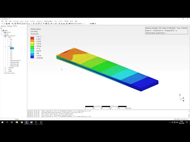
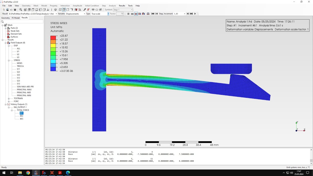
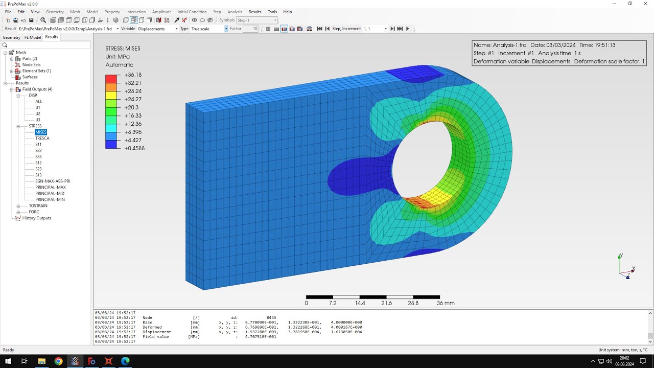
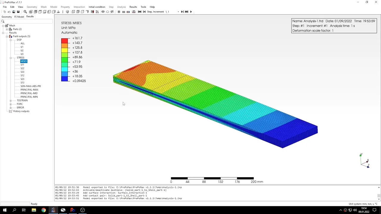
of the deflection that we expect and you can see that's pretty good if we check the deflection right here however if we decide to check the stresses you will see and that they are severely distorted you can notice that the stresses in this region of the disconnect in the region of this connection are distorted due to the constraint that was used and for that for this reason we could use different type of constraints that doesn't produce such results because we could of course ignore this region and check the stresses in further areas but this really
changes the results in a way that that we don't really want here so let's go back to the setup and i will replace the die constraint with something else let's for now deactivate this type constraint maybe of course i could also delete it but let's directly activate it and now we'll create a surface interaction and this will be contact interaction this time we'll use contact but this will be special type of contact let's define surface behavior so that's the behavior in the normal direction normally we use the hard contact type and just leave it right
like that with the default setting but this time i will switch to the last type this is tight contact we will use tight contact to simulate this connection in addition i also have to specify friction and i can leave the default value of friction coefficient it doesn't matter in this case that the value can be arbitrary so let's leave it like that and we don't have to worry about that because the contact is tight anyway it's it's a contact that can separate or slide so so that's not a problem really let's confirm this and now
i have to search for the contact press again this time i'll switch back to to contact not die constraint let's search it found the right connection i can maybe switch to adjustment and confirm this and now i have contact pair defined let's submit the analysis again it's also solved quite fast let's check the results here's the deflection in the y-axis let's compare this with analytical solution and you can check the values right here and let's also take a look at the stress distribution as you can see it's much better than in the case of of
the previous uh constraint that was used to model this connection and now there are no such effects there is no distortion of the stress around this area of connection we can also check the normal stress in this direction and we can compare it with analytical solution uh here i specified that i want the stress at the connection just for the connection so i specified the the length of the shell region and that's the stress that we expect there so let's use the query tool and verify the the stress right at this connection as you can
see and the value is is very close to the analytical solution i could also check the stresses in other regions but in this area here it will be affected by boundary conditions so it's better to check it in other locations and this region here seems like a good idea to check since previously the stresses here were severely distorted so and that's it for this prep max tutorial thank you very much for your attention as always feel free to ask any questions and suggest topics feature tutorials in the comments have a nice day and see you
in the next video