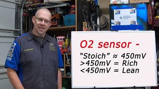
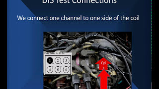
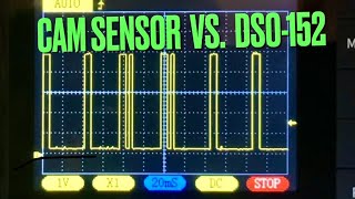
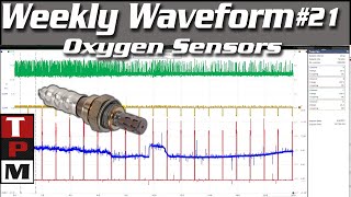
we're going to be talking about oxygen signal analysis using a lab scope you're going to use this when you suspect a fuel control or oxygen sensor problem now you may want to do this to go beyond routine diagnostics for dical problems maybe you've got a code that is difficult to clear or keeps repeating itself and you want to find out why and we're going to cover the OBD2 monitors and the type of testing they do and the results that they get with mode six now let's talk a mode about mode six we're going to use the advanced testing like the testings used by mode 6 to set oxygen sensor codes and the oxygen sensor codes are the number one reason OBD2 codes are set according to inspection programs in most of the states and we're going to cover the sensor and the heater so let's take the time now to get down into the depth of this and see how we need to use a lab scope to test the oxygen sensor and the heater when we talk about the signature analysis we're going to be using a digital digal storage scope like you see here let's take one minute to talk about the setup on this digital storage scope across the bottom you see 1 second that means we're looking at 1 second per Division and in all of our Scopes we're going to have 1 second in this particular case it's a 5-second window you'll see others where it's 10 seconds on different models of Scopes but each individual little square represented by those four vertical lines represents 1 second on other systems you will see 10 vertical lines representing 10 seconds but there each one is going to show the same picture 1 second per square now going vertically we go from zero at the bottom to one volt at the top that means each one of those three horizontal lines represents about . 25 volts with a middle one being a half a volt what you see about this pattern is it's moving smoothly about the 0. 5 volt bias now we know the stok metric is 045 volts so we can say that this pattern is moving evenly above and below Stoke geometric but one of the things we'll be doing is be looking at speed now speed here is normal activity where we're going from lean at the bottom to Rich at the top voltage is high minimum 085 volts we're rich when it's below 045 down to a minimum of 0.
1 volts we're lean now during normal activity we don't expect to see 0. 1 in 085 we do expect to see when we snap accelerate go over 085 up and we de accelerate or slow down go below 1/10th on the bottom that's called our speed test the PCM is really going to go into a specialized mode where it's going to switch rapidly from lean to Rich and measure lean to Rich switch time then it's going to switch rapidly from Rich to lean and measure Rich to lean switch time we're going to show you how to do this for your own test but its speed is between two set points a high and a low or a low and a high reaction time is the time it takes to change the signal which has been heading lean to start heading rich and vice versa a signal that's been heading Rich turning and going lean now we must Define the rich point that the minimum Rich when we go full Rich must be at least 85 volts but this can be anywhere from 085 volts into 1. 2 volts and still be normal so what mode 6 has to do is has to determine what is this Rich point at this life on this oxygen sensor so I can measure speed between rich and other points then it's going to do the same thing for lean it can go as low on some Vehicles as minus 0.
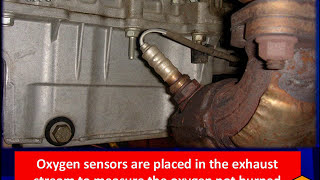
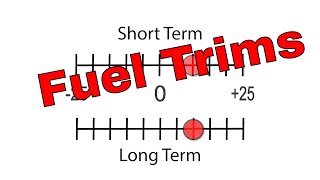
075 volts that's 75 molts minus some Vehicles don't like minus values at all you must be vehicle specific but we need to know what this point is at this life we're going to measure the time switching from Rich to lean and lean to Rich we need to know what those two points are mode is going to tell you that now the switch ratio most commonly refers to the activity of the post and padless uh post catalist and pre-cat sensors but we can also be looking at switch ratios Rich to lean lean to Rich we either going to compare for the another sensor or different phases of the sensor and then the heater operation the most common method is time to activity but you're going to see some that's actually going to measure the resistance in ohms in mode 6 and you're going to see some that's using amps in mode six others use time to mode time to activity how long does it take you to get into closed loop now let's talk about what they're actually measuring and just restate what we're looking at the oxygen sensors are placed in the exhaust stream to measure oxygen not burn during the combustion process now we know if we have a misfire we send unburned oxygen and we send hydrocarbons and while the oxygen sensor reacts with hydrocarbons and Co to measure oxygen it does not actually measure Co it's measuring the unburned fuel is based on the voltage relating to oxygen and air fuel ratios this particular vehicle we looked at here has three O2 sensors one right by the manifold which is a pre-cat one right before the Catalyst which is pre-cat and one after the Catalyst we do this for Catalyst deficiency testing and we're going to show you an absolute valid catless deficiency test but before you do any of these things before you test anything you must make sure we have normal fuel control that means if long-term fuel trim is within plus or minus Point uh 25% you can continue diagnosing now that's the official number our number we use personally is 15 to 20% depending on the age and mileage of the vehicle fairly new vehicle we want to see it within 15% older vehicle we'll give it 20 ideally before we return it to the customer we want to get it below 10 this means something has been going wrong with fuel delivery or fuel control that has been used has utilized the oxygen sensors to correct for it so don't get too far down the road before you fix fuel control and fuel delivery now once we have assertain we have normal fuel control we start judging our rich and lean now typically we see it oscillating between 0. 2 and8 volts very much like you see happening here we're going between zero and one bolt now how do we connect it we're going to hook our negative lead I mean our positive lead into the signal this is the right Upstream O2 signal on this particular vehicle it's pined number four on the O2 sensor it could be pin 60 on the PCM for this particular vehicle our negative lead we're going to show this going to ground now the most convenient ground everyone picks is chassis ground but for oxygen sensors let's talk about that it's not necessarily the best ground because this particular vehicle the PCM is controlling ignition and fuel injectors and we have a lot of currents switching off and on at this particular ground would' be much better off looking just below the red lead at Pin 91 on the PCM or on pin three of the O2 sensor and getting sensor ground it has less noise you can use either one but you will get more noise and hash if you go here which is the common place people connect here is a perfect pattern again we're back to five seconds on a screen the pattern is the same 0 to one volt it's switching back and forth in a balanced manner that means we have good fuel control and we're going to really talk more about that when we get the catalytic converters we speed it up we can speed up the whole process we can control faster it switches much faster now when you come to switching speed this is where switching speed becomes important look how straight up these lines go when you have a slow oxygen sensor it won't be able to keep up at this higher speed that's why oxygen sensor switching speed has become so important of an issue so we've defined our rich and our lean the smallest Range it can cover is . 1 volt to 085 volts Rich has got to be at least 085 volts that's when we snap accelerate add enrichment Drve the system Rich go wide open throttle on the highway we want to see point 85 volts minimum if not you've got a bad o02 sensor when we take it lean we snap accelerate and then let it decelerate for a moment we want to see it Go below 1110 you'll find these values listed as the Max and men voltages in mode 6 so when you use mode 6 you are in effect doing a pattern interpretation we would have to use a lab scope to verify when we look at the total range it's 1 2 volts Max and that's only on certain cars minus 7075 which is 75 molts almost has to stop perfectly at the zero line you will not be able to see molts very easily so you've got to be careful you don't go well below zero volts now let's talk about switch points one of the things you're going to hear in see all through O2 characteristics in mode 6 is switch point this is the ideal Rich switch point for a particular vehicle working on it's set at6 volts now what is a switch point a switch point is the spot where we start changing what we have been doing getting as the voltage has been coming up we have been stretching injector pulsewidth short-term fuel trim has been asking for more fuel when we get to 6 volts shortterm start start S asking for Less fuel as a result we see the turn and the system starts down toward the lean side if the oxygen sensor has the proper speed if it's a slow oxygen sensor we can be going richer than 14.
5 all depending on how slow the oxygen sensor is the lean switch point which is near 14. 8 to1 Airfield ratio and this particular vehicle is at 3/10 of a volt when this signal reaches 310 of a volt the short-term fuel trim is going to start adding fuel to turn it back toward the rich side we need those two points because that tells us things about reaction time if reaction time is bad we have to start that sooner the voltage will be lower at the rich switch point and higher for the lean switch point so we've got two switch points the time between switch points is measured in mode six you will see things referring time between Rich the lean switch points and lean and Rich the lean switch points in this case we're going down from Rich toward lean this is the lean to Rich switch point if we're going the opposite direction coming from lean going to Rich this is the time between lean to Rich switch point nice to know how balanced these numbers are if you have a great deal of imbalance between lean to Rich and Rich to lean it means it's bi in One Direction or the other and you're probably going to find a long-term fuel trim is up higher than we want to have it than saying plus a minus 25% before we can even start this test big slope is a measurement Chrysler does which is measuring the volts per millisecond between the rich points it's the rate of change volts per time you're going to have them from between the lean switch point and the rich switch point what is the minimum lean voltage this is a value we need to know if we're going to do some other testing it's got to be below . 1 volt remember then the max Rich volt it must be above 085 this tells you how far you're going each Direction so we're going to start testing our O2 sensors but I want you to look at something here on this lab scope first we got to identify a few things we're looking on the green scale at 1vt signal as soon as we start testing we found out very quickly we need to pay attention what's going on now I want to talk about the scales look on the left side of this the blue writing is for the amperage our blue Trace is between zero and two that's just slightly above 1 amp our green Trace uses the green numbers it's between 1 and 2 volts notice this scale goes from -3 to plus 5 why are we're reading so high this reads 1.
5 voltage is this a problem or is this normal we want you to consider all that and we keep stressing using manufacturing specific information here's another pattern that looks like it's wrong on the left we see that we're on a minus5 to plus 5 volt scale that means the middle of the screen right by the big V is 0 volts so this pattern is going between 0o and about 3. 3 volts that definitely violates everything we said we're going to see on these cars so you pay attention when the scale is different and we has to be different to work on this car this particular vehicle happens to be a next Generation controller O2 signal from Chrysler you're going to see different values than you saw before in fact when you hook your lab scope up your values are going to change slightly anyway you're going to have to really really use scan data to really evaluate both of these and we'll show you why later on notice here this is a jtec Jeep truck engine controller where we have a separate engine controller and transmission controller it started off above 1vt and as it warms up it moves on down and then pretty soon it goes in the closed loop and starts looking like a normal oxygen sensor so be aware of these differences but once we start looking at this and we eliminate jtec before it warms up we eliminate Next Generation controller Chrysler for GM Chrysler begins to look the same stokum metric is going to be in the middle now notice here we start at zero in the middle and go to one volt when our green scale stokum metric is in the middle that's the ideal point we have switch points high and low and we're going to Define all of this but we're going to say it one more time just to remind you do you have good fuel control because we're going to show you some cases with scope patterns where it's not we're going to show you why here is poor fuel control let's talk about the voltages this signal is ranging between 04 and 0. 55 volts it's the same 10 seconds we've been looking at we got 1 second provision we got 10 seconds this vehic this is not in fuel control now question is is it the sensor is it fuel control or is it fuel delivery remember we divide fuel Fu control into the mathematics we do based on mass air flow and everything else to compute injector pulse whip fuel delivery is putting fuel Lively to that injector so that you get the right amount of fuel or that pulse width if the pressure's wrong the volume's wrong the injector's dirty we've got a problem what about the O2 sensor well what's going to happen the way the computer is going to handle this is during the process the PCM is going to shift the air fuel Rich Lan to test for O2 operation get the max and M we're going to do the same test only we're going to use throttle changes operating speed O2 sensor speed is in theorder because the PCM determines if fuel was delivered for acceleration how can it tell if it's slow it can determine if fuel was shut off for deceleration if it's slow it loses that information the PCM can keep air fuel ratio correct during steady throttle to reduce emissions all these are only possible with proper speed of the O2 sensor the O2 speed is one of the most overlooked part of sensor testing and unfortunately we cannot tell you any way to do it other than using a lab scope now Forge Mode 6 calls it an amplitude test and we're going to explain this rather complex thing here we've drawn a line at 0.
5 volts what Ford does is go from lean to Rich very quickly and in this blue box is the time they start the test to the time they end the test the left side's when the test starts the right side's when it ends a is a sensor that's very fast it goes out of the box at about 6/10 of a volt B goes out of the box at about4 volts C goes out at . 1 volts C is a very slow sensor now remember fuel has changed we've gone from lean to Rich the question is how long do it take the oxygen sensor to see that change let me say that one more time we've gone from from lean to Rich how long does it take the oxygen sensor to see that change a sees it right away it's a brand new sensor b doesn't see it for a while and C is a real bad cat he hardly ever makes it he never really catches on we've already changed and gone somewhere else before c catches up and if we're normal high-speed fuel control we're going from Rich the lean before B even catches up the rich site that's why we fail so many oxygen sensors in im240 it's the number one failure combine all the oxyen failures into one failure they outpace everything else in California Wisconsin Massachusetts Indiana anywhere you want to go the O2 censor is the number one cause of service codes on OBD2 cars let's look some more at this how do we do this test now we're taking our same go pattern we captured one we let the pattern go down to the lean side and then we snap the throttle open and you see the change start at the bottom you see it at the top we want to see nice straight patterns does that look like the a pattern we just showed you this is the way we duplicated so if mode 6 or trouble code says you have slow O2 this test can verify you have no fuel control we in dead weird we got to start testing oxygen sensor fuel control fuel delivery let's start with the O2 sensor snap the throttle wide open to see if the O2 sensor responds what should happen well first of all we're going to get enrichment and Go full rich if we can respond quickly go to fuel control is the calculation right go to fuel delivery can you deliver the fuel to the injector when it's open the proper amount or do you have to add a bunch of long-term fuel Trim in to overcome low fuel pressure dirty fuel filters weak fuel pump dirty fuel injectors you have to add fuel in to overcome mass air flows that are dirty or any other of the sensors that are critical to fuel control if the doesn't respond it's easy change the sensor now this may seem like a real dumb thing but we find a lot of people going in the ditch here if we can't get good fuel control and good delivery we need to replace it and we've divided the sensor from the rest of the system by doing this test O2 heater operation if the oxygen sensor doesn't go in the normal operation soon enough test its heater circuits you may also have a code and information in mode 6 telling you about that either way we're going to see what we have to do to test it our method of testing it is to use a low amp Curr probe as you can see here we're looking at at a purple and white wire and showing you where it is on the actual oxygen sensor itself we're going to clamp around that wire we can EAS use a positive side or we can use the ground side here if you want to capture the maximum current flow the engine should be cooled we're going to read the amperage and measure the o2's heater current now the question is is this 2 1/2 amps normal high or low well first of all you need to know something just take Ford as an example Ford has four different heater current specifications for very narrow range of vehicles we know Chrysler's got a dozen or more the real message is when you have it available use mode 6 to tell you what the specification should be you can look at the max and minimum limit information to see if this is normal or not in our book it's slightly higher than normal which is going to take us directly to the O2 sensor itself but if it's low we're going to have to do some circuit testing before we condemn the sensor first we're going to check for B+ at the heater here we're looking at 12. 8 volts which is what's battery voltage we put our voltmeter on pin one and our ground lead on engine ground battery negative and we're also going to check the ground circuit now the first indication anybody that knows us know that we like to see 50 molts in ground this is 321 molts but look just above the voltmeter to the right and it says that ground has duty cycle control so that may look like a bad voltage that's why we use current flow now the heater operation changes between manufacturers vehicle specific information is important because there are major differences I'm going to show you using Chrysler between espec Next Generation controller and jtec Jeep truck engine controller now here is a GM heater warming up as you notice we first started to turn it on going to our scope we are on a half second per division 5 Seconds across the screen the green scale on the left is 0 to 10 amps we are looking at around 1 amp little less than 1 amp about a half amp yeah let's blow it up so we can see it now we're looking at you can see well less than a half an amp this is normal for a restart but we've got a couple blips in the middle we need to understand what those are we'll talk about it if you have no current flow go check the fuse but this is normal activity and looking at this normal activity we see that it's being turned off by the PCM what the PCM is doing current flow goes to zero when PCM ungrounds the control for the ground that's why ground voltage is higher than normal not all vehicles have that if you have a problem where you can't get good current flow check for normal grounds you have to have good grounds in order for them to draw full current flow early crisis systems ran the heater current test after 6 to 12 minutes after engine shutdown now you could watch the monitor if you could ever catch it running we tried for years and never could catch it running but why wait so long why waste time we can run our own test here is an esec and we're going to break each one of these signals down right here in this red box is our startup we've gone on the left of the red box key is off we start the engine start it running and start recording the information on the right now the green relates to the green on the far left scale we have zero volt at the bottom 14 volts at the top it's 14 volts this is Ground Control when we remove the ground we go to battery voltage we Supply the ground we go to zero volts so that's normal activity right up the startup lots of activity limiting current flow battery voltage comes up stays at 14 volts once the car gets started into steady but look at the current flow at the bottom it's varying from 1 amp to 0 amps notice the Little Black Arrow when the ground is supplied we have one amp of current flow but notice what happens after the car has been running for a while we turn Ground Control off and give it a ground all the time we see here running a steady current flow it indicates a good sensor the lack of duty cycle at startup would indicate to you that you have something wrong because you should be limiting current flow on a coold sensor limiting current flow is not needed once the the heater element heats up here it is on a jtech start the car up starts running soon as the car starts up starts running we turn the heater current on and it just starts going downhill slightly if you look very carefully we magnifi it here you can see we start off at about 1.
8 amps of current flow and then it tails off that's normal activity here we turn the key on started the car and it tailed off this is normal activity we can see what's going on there in this particular case this is a Ford with the current settled down at about 1. 06 amps or about 1 amp did not need any duty cycle so you'll have some that's duty cycle some that are not some Vehicles like jtec have a special operating mode to identify heating failures they have a 5vt pull-up like here on the left the pull-up resistor will drop down to below one volts when the heater warms up the resistance of the element in an O2 sensor drops R drastically as it warms up it's using that capability now on the right we have ESC it's very much like most Vehicles 45 volt pull-up but here's something you need to be aware of we have our scan tool here the red arrow now is pointing to the voltage on the right in the spot on the left where the little dotted line is reading the voltage we have a DSO connected digital storage scope is connected a digital storage scope is only 1 megaohm input resistance it can cause readings to be lower than normal it will pull the voltage down slightly particularly in high amp High resistance circuits like this one when we disconnect it the voltage goes to 4.