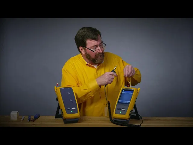
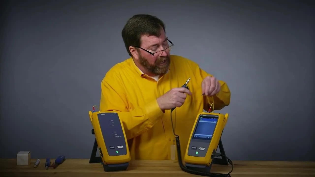
hey good morning everybody Jim Davis here from the fluke Network's technical assistance center I'm excited we got something new to talk about testing today we're going to take a look at how we test this new you might have heard of it as a vssf or a very small form factor connector there are a couple different types today we're going to be taking a look at how we test an MDC connector and something really interesting I have an MDC input on the port of our versive certifiber Pro so we can set a one jumper reference which
of course will give us the least uncertainty in our measurement now to do that we've got to catch there are two connectors in here there are two ferals and I've got an output port and an input Port so to overcome that we're going to be using this y cable one leg will be our transmit and the other will be our receive I want to take a moment to thank L Grand who supplied us with both the Y cables and the cables that we're going to be testing today as part of their ACC Claim Solution and
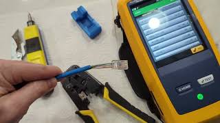
hey instructions for how to test a claim all right so now let's get our one jumper reference set so to do that I'll take our connector out we're going to take off our dust cap and hey I tell everybody they need to inspect before they connect so let me make sure I inspect before I connect myself I like to hold the connector and use a finger from the hand that's holding the connector to try and line this up plug this in I do have a fiber inspection test set so we'll push the fiber inspection button
and we'll just get that in Focus beautiful that's ready to go now we're used to LC connectors that have a horizontal orientation but these MDC connectors have a vertical orientation so I'm looking to see where this key is along the top Edge and I need the key to be on the right hand side because what I'm going to do is line up one of the legs with the photo detector inside of here so there is one leg lined up and let me not get my cables confused here not that that would ever happen take off
our trusty dust holding cap just because it has a dust holding cap doesn't mean it's clean so let's again use a finger here line this up slide that on once you've looked at a couple of connectors you'll understand that's clean and ready to go again with the black key facing to the right hand side of the tester that will line up the fiber we get the happy noise great so now I'm going to go to the home screen and I'm going to switch from my fiber inspection test to my fiber loss test doing Smart Remote
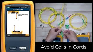
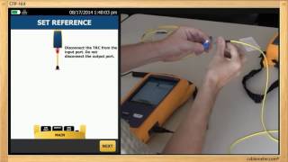
of an optical loss test set in olts we'll say use selected now when we're doing fiber loss testing the first thing that we need to do is measure how much light is coming out of the fiber now we call this setting the reference setting the reference is an extremely important step if we do this wrong our testing all day long is going to be wrong that's why we want to do this with the one jumper reference now one of the things that I really like about the certifiber pro is when I go into set reference
I have this wizard to walk me through the steps so let's jump a couple steps in here and we'll see black boot in the power meter red boot going to the output Port heck and even has yellow fiber to remind us that we're doing single mode so we remember to plug into the single mode output and not the multi mode all right and next we'll say set reference and nice thing about the wizard is if the reference is wrong the tester will bark at you and say hey there's not enough light if we want to
we can view the reference about minus 3 dbm that's what we're looking for go back into our test now next it's going to show us to disconnect from the power meter now here's a trick when I disconnect from the power meter let me think about where I'm going to go with the fiber so I don't want to disconnect it and say where's the coupler where's the cleaning kit and wave it around and get a bunch of dust on it so I'm going to put these into this coupler I'll take this out now on the coupler
I'm looking for the side that has a hole in it as opposed to the side without a hole and I'm going to align the side with a hole with my key that's going across the top of the connector we'll plug that in now little bit of a tricky part and what I'm doing is the test reference chord verification here to pull the connector out I need to pull it by the boot and I need to reverse the polarity otherwise I'll have transmit to transmit so to reverse the polarity of the connector just going to hold
the blue part here here pull down on the strain relief and I'm going to rotate the connector and with a little bit of practice you'll get better at sliding this in there we go it's locked in place and now you can see that MDC is upside down relative to the key now because this was in the power meter that isn't making physical contact I'm not going to inspect the connect right now generally these work well for me all right now that's plugged in now we do need to plug in the other leg now in the
other leg even though there seem to be two ferals here we're only using one of the fibers the other fiber is on our transmit leg so I just need to inspect the one fiber that's next to the key to make sure that that's good now here is a fun enhancement in the 6.12 firmware you'll notice now I've got a fiber inspector button so if you forget about the secret button and if I got to call it a secret button who's going to know it's there I can inspect this in the middle beautiful and again I'm
going to have the black key going towards the right I can inspect these connectors in the middle of the set reference wizard without having to jump out of the wizard add this to our collection of little pieces that we don't want to lose and again I'm just inspecting the one fiber because there's nothing on the other leg good enough all right and with the key facing to the right we'll plug this in and because I reverse the polarity we get the beep the happy noise now the test reference chord verification is just to check and
make sure that these connectors are high quality with the new very low loss budgets that we have we want to reduce the uncertainty and the better the performance of our test reference cord connectors the less uncertainty we're going to have in our measurement so now a new enhancement from the 6.12 firmware our back button is highlighted we want to Follow the yellow brick road too many wizard references here but typically the yellow button is the Preferred Choice I'll add my known good leg here and we'll join those together and we'll do our test reference course
word verification now because this is single mode yep we want to get less than 0.25 DB of loss we've got that now we're ready to take our measurement we'll just finish up the wizard The Wizard says open it up and put our link to be tested there all right so hey I want to do things the right way and even though I have inspected our link to be tested a couple dozen times already we're going to in ECT it again I'm going to do a bulkhead inspection because that's a little bit different and to do
the bulkhead inspection I'm partial to using our fi 3000 camera the FI 3000 camera has two real benefits over the single fiber Fi Fi 1000 and the first benefit is if I am using an Mo connector or an MMC connector this will be for the next video the FI 3000 allows me to see all 2 four fibers in this Mo connector at a single time the other thing that the FI 3000 camera does really well is Bulkhead inspection I find with the single camera it's a little bit trickier I kind of wish I had a
third hand to adjust the focus when I'm when I'm plugging it in so for this bulkhead inspection I'm going to put this little tip into the bulkhead now remember this would be in the Rack in our patch panel it's not going to be in our hands but for purpose of this demonstration it's going to be in my hands now there are two holes because they are two fibers and what we're going to do is first remember to turn the camera on and then we'll slide the tip of the camera into the first of the holes
now the camera will also work better if it's plugged in yeah you'll forget this but then you'll realize and I'm going to change from my lost test to a fiber inspection test you selected push test to start now at first we're going to see it showing up just as this little tiny dot that's okay because remember this camera is expecting to see a row of 12 fibers so we'll say analyze and instead of getting that low resolution image we'll get a high resolution image that'll show the whole connector and face beautiful and then of course
we'll switch over and test the other connector because they're two to make sure that both of them are in good shape now I'm not going to save these these images and that's just a choice do I need to save the images or not it depends on it passed that's nice it depends a little bit on your contract does your customer want you to save all those end faces and I kind of think you know GE a passing endace that's some that's not the most exciting thing but think about it what's going to be done with
your link after you leave and if someone's going to come along in a week a month a year to plug in some active equipment you might want to save that nface image so that when the next person who comes along to plugs to plug in if they screw something up and how are they going to screw it up they're going to plug in a dirty patch cord if you've saved the endace image you have documentation to say hey when I left this was in good shape and it's not that you won't have to come back
it's just that you won't have to pay for the return trip all right so now that we know that our connector is in good shape and for the sake of this video work with me on this I have a reverse polarity I have a flip in the link to be tested so I'm not going to change the polarity back of this connector I am going to make sure that the key is lined up with the hole along the top and I'm going to make sure that the key is is lined up with the hole on
the top of the coupler on the far end and we'll plug that in got the happy noise that's a good sign that means we're lined up the right way now let me go back to home and I'm going to go back to doing our loss test with the Smart Remote use selected now I'm doing the ref version the difference between ref and standard is reference grade knows that we're using connect conectors with better than 25db of loss so it's only going to give us 5db of loss for the first and last connector when we think
about the high-speed applications this is a better way to go all right and we'll push test to start 3 seconds two wavelengths we passed that is a one jumper reference setting and testing of the new very small form factor MDC connector thank you for watching