hello and welcome to my next tutorial about prepomix a new version of this software came out today and the biggest new feature is support for two-dimensional analysis and in this tutorial i would like to show you how to perform a plain stress analysis on a u-shaped member let's create a new model first and now you can see that there's a difference in this window because apart from selecting a unit system type you have to also select model space so this can be 3d or 2d and this is either plane stress plane strain or axis symmetric
and for today we will need plain stress type so we'll choose this one and millimeters standard unit system and let's import the geometry as always as you can see geometry that i import is like a shell it's a flat geometry kind of surface and this was prepared in free cad and i will show you how this model was prepared i had to do some non usual operations uh i created a sketch first and that's the schedule some additional construction lines to to let me measure various dimensions for the analytical solution anyway that's the the sketch
then i extruded it in actually padded because that's how it's called in freecad and then i used draft module and option to downgrade the downgrade the geometry and this created multiple faces i deleted all the faces apart from this one here and then i had to do one more thing because if i import the part right after downgrading it this will be incorrect geometry and if i import it to prepomex then the normals of the elements generated for this part will be inverted so in order to avoid this i have to perform some additional operation
and this is important i have to go to a part module and select this this face and use the tool to reverse shapes and then if i export the reverse shape the part will be correctly imported and they will be able to generate the mesh properly so that's it when it comes to the preparation of this part also keep in mind that in order to create two dimensional models in in preparamex in in calculus in general uh you have to draw the on x y plane so the z coordinate have to be zero uh and
that's pretty much it for plane stress models um for axis metric models there are some special considerations in addition to the one discussed here but we will go into that later on so now let's create a mesh for this part i will specify maximum element size of one millimeter and now i'll measure this part i should also mention that two-dimensional heat transfer analysis are also possible in preparations now but we will go to that in future tutorials now let's focus on this example of plain stress analysis and now i will create an old set uh
for this hall number one i will choose the uh edge angle base selection and i will pick this edge here this will select the whole the whole hole right here let's confirm this and i will choose i will create another node set and this will be done in the same way but for this hole right here and let's confirm this now now we have two sets so that we can use for uh loading let's create reference points now uh i will choose the method to create them by center of gravity and all specified notes of
name this will be hole one for the first hole and this will the reference point will be placed right in the middle let's confirm and now i'll do the same for the second note set and the reference point will be created in the correct position now let's create ridge body constraints because that's why we needed the reference points you can notice that there are some additional constraints point and surface springs we'll also discuss them later on let's create a ridge body constraint now i will specify the node set name and this will be the first
virtual body constraint and the second one will use the reference point number two and node set number two so we have the rigid body constraints defined now so let's proceed to material definition something we always have to do of course so this will be standard steel material and now i have to define section and there's a difference because now even though it's a solid section not shell section and by the way you can also notice that membrane sections are now available i have to specify thickness even though it's solid section because we are in two
dimensional analysis is a plane straight case plane stress case so i have to specify thickness and thickness in this case will be five millimeters so i will confirm this now and i just have to create a step this will be standard static step nothing change here and let's create loads and boundary conditions for this analysis let's start from loads i will use concentrated forces applied to reference points let's pick reference point number one and the magnitude will be 2 000 newtons that's for the first reference point and now the same for the second reference point
the same magnitude but in opposite direction so we will have such two forces now let's define boundary conditions i will specify displacement rotation boundary condition i can hide the mesh for now and i'll use so-called three-to-one methods uh actually in this case it's it's not full free to unlock because it's a two-dimensional case uh but you can call this also minimal constraint method and anyway and it's a special way of constraining models to avoid rigid body motions you can read about it in various articles online it's an interesting approach to boundary conditions in fva so
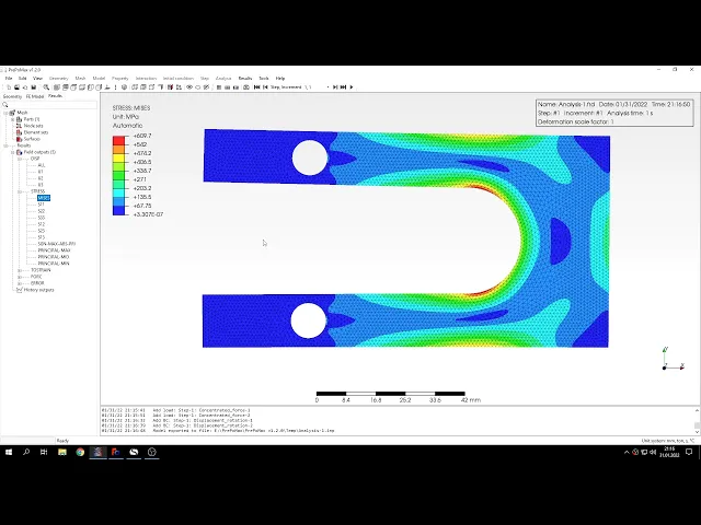
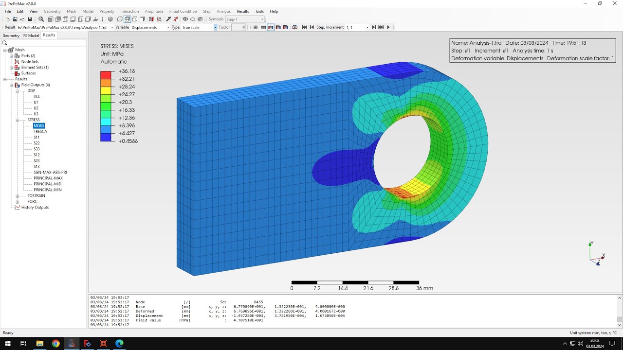
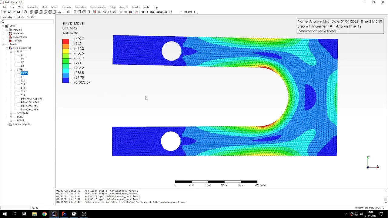
let's constrain this point only in y direction and this point right here in both x and y direction so now the model is prepared and i can submit the analysis like we always did as you can see the results are already already available the analysis was really short that's thanks to the use of two dimensional approximation if it was 3d it would take much more time anyway here are the results the stresses we are interested in maximum stresses let's check the analytical solution here you can see the dimensions of of the whole part and the
unit solution is based on peterson's stress concentration factors and here the two stresses that we expect to uh to find in the analysis is sigma a is for this section while b is for this uh a lot of section aligned like this so let's the the angle here is 20 degrees i should mention this uh so let's go back to into the analysis and use the typical query tool to measure the the stresses in those two locations that i've showed you before the stress here is as you can see around the expected value it's pretty
close uh a bit lower but but pretty close to what we expected from from the theoretical solution so now let's check the other value and this is somewhere here we can choose a few a few points around this location because we can't be sure where's the the angle of 20 degrees so let's check a few points around this location and you can see that we are if we check the if we select the the points on this perimeter and then we are pretty close to what we expected from this analytical solution and there was one
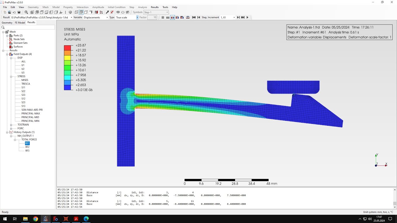
point where the value was very close here so that's how we can compare this to the electrical solution i can also show you one more thing if you want because for now the results are displayed like this since it's a two-dimensional analysis but if you want to uh to extrude it or see the actual thickness and then you can go to field outputs element field output and you can choose a three-dimensional output here and you will notice what happens when i uh submit this analysis once again and now you can see and that the results
are displayed in three dimensions accounting for the thickness so uh that's it for this preponderance tutorial thank you very much for your attention as always feel free to ask any questions and suggest topics for future results in the comments have a nice day and see you in the next video