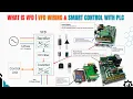
[Music] Have you ever wondered how industries save 30% energy costs or more while keeping motors running smoother and machines lasting years longer? Do you know the secret behind it? It's called variable frequency drives or VFDs.
But here's the thing. Most people have no idea how the VFD actually works and why they're better than other starters like Star Delta or Direct Online. In this video, I'll break down exactly how a VFD works, how it saves energy, and the most common reasons VFDs fail, plus how to troubleshoot and fix them with ease.
I'll also show you how to wire and program a VFD step by step. I'll even cover real world fault examples like overcurren faults, ground faults, communication failures, and short circuits. Your VFD could fail, costing you up to $10,000.
Don't let it happen. Just stick around and I'll show you exactly how to avoid it. And don't forget to like and subscribe for more practical videos.
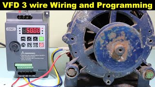
Okay, before moving into the details, let's understand the basic working of a VFD. A variable frequency drive controls the speed of an electric motor by adjusting two key parameters like frequency and voltage. To demonstrate this, I'll now adjust the VFD to different frequency set points step by step so you can clearly see how the motor speed responds.
I'm setting the frequency to 10 hertz. Watch closely how slowly does the motor rotate at this level. This is because lower frequency means lower motor speed.
Now let's increase the frequency to 30 hertz. You can see the motor spinning a bit faster. Now it's still not at full speed.
Next I am raising the frequency to the standard 50 hertz. This is the rated speed for most motors. And now the rotation looks steady and smooth.
Let's push the frequency higher to 60 Hz. Look at that. The motor spins even faster.
That was a quick overview to show beginners how a VFD affects motor speed. It's the starting point for understanding motor control in real industrial systems. Okay.
I'm going to show the practical impact of a variable frequency drive in an industrial setting by showing how a water tank is filled using a VFD controlled motor. I'll also compare it with a traditional DL starter to highlight the differences in performance and efficiency. Okay, I'll change the speed set point in terms of frequency to show how the water flow gradually changes with motor speed.
Let's begin by setting the frequency to 10 hertz. At this low speed, the motor rotates slowly and water flow is minimal. This shows how a VFD gives fine control at lower speeds.
Now increasing to 20 hertz, the motor picks up speed and you can see the water flow gradually increasing. This prevents sudden surges and saves energy. Next, we move to 30 hertz.
The motor runs at a moderate speed and the flow becomes steady. This level is commonly used in many process applications. Now at 40 hertz, the motor is running fast and the water flow is strong.
You can clearly see how speed affects the output. Finally, we apply 50 hertz. The motors rated full speed.
The water flow reaches its maximum. This stepbystep increase shows how smoothly a VFD controls motor performance. Now let's see how the motor starts using a DL starter.
As soon as the DL is energized, the motor receives full voltage instantly. This causes a sudden jerk and a very high inrush current up to six to eight times the normal running current. You can see the motor starting with a sharp jump in speed and water flow.
This puts stress on both the electrical system and mechanical components. Unlike VFD, there is no gradual ramp up. This is why DL starters are less efficient and can lead to faster wear and tear over time.
With a DL starter, the motor runs at full speed immediately, so the water tank fills faster. But this quick operation comes at a cost. high inrush current and continuous maximum power usage even if full speed isn't needed.
In contrast, a VFD controls the speed based on demand, saving energy by only using what's required. So, while the DL may seem faster, the VFD is much more efficient and cost effective in the long run. Now it depends on you that would you prefer to fill the tank faster at a higher energy cost or wait just a few more minutes and save electricity with higher efficiency.
I believe you'll make the smarter choice and that choice is the VFD. A variable frequency drive controls the speed of an electric motor in a smart and efficient way. It all begins by converting incoming three-phase AC power into DC using a rectifier circuit.
This DC power is then filtered and stored in large capacitors forming what's called the DC bus. Next, the inverter section comes into action. It takes the DC voltage and converts it back into AC, but this time with adjustable frequency and voltage.
To do this, the inverter uses PWM or pulse width modulation to rapidly switch power transistors on and off. This generates a simulated three-phase AC waveform to drive the motor. The control circuit manages this whole process.
Before moving into the bridge rectifier explanation, let's quickly go through some essential safety guidelines. Before starting electrical job, always make sure the power supply is turned off before touching any electrical connections. Make sure there is loto lock out tag out to ensure isolation.
Use insulated tools and wear appropriate personal protective equipment including safety gloves and goggles. Double check all wiring to avoid short circuits and never bypass protective devices. Remember, even low voltages can be dangerous if handled carelessly.
Turn your attention to accident prevention. Be aware, take care. Now, let's move on to understanding the bridge rectifier.
Before we start learning about the three-phase bridge rectifier, let's first recall the basics with a single-phase bridge rectifier. In a single-phase rectifier, we use four diodes D1, D2, D3, and D4 arranged in a bridge configuration. These diodes work in pairs, allowing current to flow only in one direction through the load regardless of the AC polarity.
During the positive half cycle, two diodes conduct, sending current through the load. In the negative half cycle, the other two diodes take over, keeping the current direction the same. This simple principle of diode conduction forms the foundation for understanding the three-phase bridge rectifier where the same concept is extended using six diodes for smoother DC output.
Okay, we are going with with a three-phase AC supply consisting of three lines L1, L2 and L3. These are connected to six diodes arranged in a bridge configuration. The load is connected on the DC side where we expect a constant smooth current.
AC voltage constantly changes polarity, but a diode only allows current to flow in one direction. By arranging these six diodes in pairs, we ensure that no matter which AC line is at the highest potential, current always flows in the correct direction through the load. The conduction happens in six steps per AC cycle.
First cycle when L1 is at the highest potential and L3 is at the lowest D1 positive side and D6 negative side conduct. Current flows from L1 through D1 across the load and returns via D6 to L3. As the voltages shift, L2 becomes higher than the others.
So, D3 and D6 conduct, directing current from L2 through the load to L3. Next, L2 stays positive, but L1 drops lower. So, the conduction path switches to D3 and D2 with current flowing from L2 through the load to L1.
As the waveform progresses, L3 rises to the highest potential while L1 is lowest, making D5 and D2 conduct. Current now goes from L3 to L1. Then L3 remains positive but L2 drops lower activating D5 and D4 transferring current from L3 through the load to L2.
Finally, when L1 becomes higher than L2, D1 and D4 conduct, sending current from L1 through the load to L2. This sequence repeats continuously with two diodes conducting at a time, switching pairs every 60 electrical degrees. As a result, the load see the pulses of current that never reverse direction, creating a pulsating DC voltage.
When filtered with capacitors, this DC becomes even smoother, ideal for powering electronic circuits and industrial drives. This is how a three-phase bridge rectifier efficiently converts AC power into a stable DC supply. Before moving to VFD interface with PLC and VFD common faults, let's summarize the VFD in block diagram.
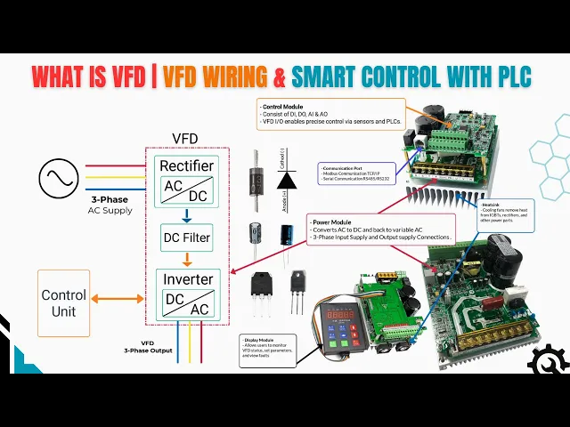
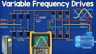
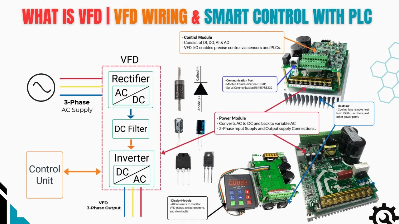
VFD mainly consists of three sections. the rectifier, the DC bus and the inverter along with a control unit that manages the entire operation. First, the rectifier stage takes the incoming AC supply and converts it into DC.
This is typically done using a diode or thyroster bridge. The output here is an unregulated DC voltage. Next, this DC flows into the DC bus where capacitors and sometimes reactors smooth and filter the voltage, reducing ripples and storing energy.
The DC bus acts like a stabilizer, ensuring a clean supply for the next stage. Then comes the inverter stage where the DC is converted back into AC, but now the output has a variable frequency and voltage. This is achieved by high-speed switching of IGBTs or transistors creating a pulse width modulated waveform that effectively controls motor speed.
Finally, the control unit monitors and adjusts the operation. It takes signals from the motor and process sensors, processes the data, and precisely controls the inverter's switching to achieve the desired motor speed and torque. As you can see, a variable frequency drive consists of four main hardware sections.
The control module contains the microprocessor and IO interfaces. It processes feedback signals and executes control algorithms to precisely regulate motor speed, torque, and protection functions. The power module includes the rectifier, DC link, and inverter.
incoming three-phase AC on terminals. R SNT is converted to DC stabilized and then inverted into a PWM controlled AC output on UV and W to drive the motor. The cooling system uses heat sinks, fans, and temperature sensors to dissipate heat from power semiconductors like IGBTs, ensuring safe thermal operation.
Lastly, the display module provides the operator interface for parameter setup, monitoring, and diagnostics. Together, these modules enable efficient and reliable motor control in industrial applications. One important fact is that a variable frequency drive VFD saves energy by controlling the motor speed according to the actual process demand.
In systems like pumps and fans, energy consumption is proportional to the speed of motor. Therefore, even a small reduction in speed leads to significant energy savings. In contrast, a direct online dwell starter always runs the motor at full speed regardless of load, resulting in maximum power consumption and high starting currents.
A VFD operates differently. It ramps the motor smoothly and runs it only as fast as needed to complete the job. Now, let's compare two motors with pumps of the same rating, filling the same tank.
one using a VFD and the other using a Dwell starter. I am giving the start command to both motors. Let's see which one fills the tank faster and at a lower cost.
The DL starter only takes high inrush current during the first cycle and then stabilizes. It still operates the motor at full speed regardless of the actual demand. This means the motor continues to consume nearly the same amount of power even when the process requires less.
You can see that with do it took 30 seconds only while the cost was high in term of energy consumption. In contrast, a VFD not only eliminates the high starting current, but also adjusts the motor speed according to process needs. By running the pump or fan at the optimal speed rather than full speed, the VFD significantly reduces energy usage.
According to the pump and fan affinity laws, even a small reduction in motor speed can lead to a large reduction in power consumption. Over time, this controlled operation results in up to 30% or more energy savings, proving that VFDs deliver the same output as Dwell starters, but at a much lower cost and with less mechanical stress. In industries, there is the margin in process that if tank is filling at 1 minute and 302, then it's acceptable as compared to 302nd with high electricity bill.
that why VFD are preferred in industry to save electricity bill. All right. Now I am going to show you something more interesting how industries handle the control for VFD and Dwell starters.
You can see there is a PLC that controls the process through both the VFD and the DL starter. To control the VFD using a PLC, you can use two methods. Number one, you can interface it with hard wiring using 4 to 20 milliamps or 0 to 10 volts for command and feedback as you can see here.
Secondly, you can communicate with the VFD through serial communication or Modbus RS232 or RS485. Using Modbus, you don't need any extra wiring. The only requirement is an Ethernet cable to connect the PLC end and the VFD end.
You can comment if you need PLC programming for VFD and DL starter. I can help you out with Modbus. You can read all the parameters like voltage, current, command and feedback.
Similarly, you can send all the commands using Modbus to operate the VFD and monitor it directly on the HMI. I'm going to show you something practical how industries control VFDs directly from an HMI. On this single HMI page, you can see multiple pumps and each motor is controlled by its own VFD.
Watch closely. When the operator enters a set point, the VFD determines how much time it needs to reach that value while optimizing energy usage. For this demonstration, I'll control this pump using the VFD by giving it a start command at 55% speed.
See how the motor smoothly accelerates to reach the set point. Notice how the current also rises gradually. This is how a VFD efficiently maintains process variables like level, pressure, and flow while saving energy.
Okay, let's get back to our animation to clear your concept with details. We have discussed VFD, but on the other hand, we have DL starter which also getting start command from PLC digital output card and giving motor running status feedback to PLC using digital input. C both pumps started and playing their role based on their starting modes.
One pump filling the tank at lost cost in term of energy consumption and one pump filling the tank at high cost with high energy consumption. I hope you get to clear understanding and general concept for VFD integration with PLC. Now let's talk about the common VFD faults that people often face because of a lack of hands-on experience or any other reason.
This video will help you to handle the VFD issue and troubleshooting. Please don't forget to comment your feedback about this video. Let's start with VFD grounding issues.
One of the most common problems you'll find in VFD and motor systems across the world. A ground fault occurs when electricity leaks to Earth instead of following its intended path. In VFD systems, this can trigger alarms, trips, electrical noise, and even cause expensive damage such as IGBT failure.
The main culprits are damaged insulation, loose connections, or moisture ingress, which allow current to escape. Detecting ground faults early with insulation resistance tests and proper grounding is essential to prevent downtime and costly repairs. Most VFDs use residual current detection, monitoring all output conductors with current sensors.
If the imbalance exceeds a set threshold, often around 100 milliamps, the drive trips. While small capacitance differences in cables can cause nuisance trips during commissioning, later faults are usually real. I am showing you in writing to well understand the concept.
Please read once to get technical understanding. Highfrequency noise and standing wave spikes from the drive can also trigger trips if cable shielding is poor. Using steel conduit instead of shielded cable can be risky.
Over time, corrosion may weaken the ground path, forcing noise currents through alternate resistive routes and causing imbalance. Sometimes the root cause isn't the cable, it's the motor. Motors can fail due to voltage spikes, overheated windings, deteriorated insulation, or an external conductive object creating a path to ground through the windings.
Once the windings are compromised, rewinding or replacing the motor is often the only solution. To confirm the source, power off the system and disconnect the drive's output leads. Then, power the drive back on and issue a run command.
If no fault appears, the motor or cables are to blame. But if the fault persists, even with the leads disconnected, the VFD itself likely has an internal failure and may need replacement. Cable insulation damage is a major contributor.
It can result from overheating after overcurren events, bending or pulling in flexible cables during installation, or even physical damage from pests. Once insulation breaks down, current can bleed to ground whenever the conductor touches earth potential. The best practice is to test cable insulation using a meggometer to confirm the integrity of motor leads before restarting the system.
In short, early detection, proper shielding, regular insulation testing, and correct fault isolation procedures are the best defenses against ground faults and the costly downtime they can cause. Okay, the most important problem is bearing failures in VFD-driven motors. And what you need to know, one of the fastest growing causes of electric motor failure today is bearing damage linked directly to VFD operation.
The culprit is fast rising voltage pulses and high switching frequencies. These pulses always search for the path of least resistance to ground. And unfortunately, that path often runs right through your motor bearings.
Over time, the repeated discharge of these currents scars the bearing races, leading to costly and unexpected breakdowns. Most importantly, why it happens? Highfrequency pulses from PWM switching in the VFD generate parasitic currents inside the motor.
This leads to EDM or electrical discharge machining where microscopic arcs pit and flute the bearing surfaces. The more it happens, the faster the damage escalates eventually leading to complete bearing failure. And the main sources of bearing currents are circulating currents are created by shaft end voltage from unbalanced stator magnetic flux.
Shaft grounding currents flow through the bearings to ground via the driven load. Capacitive discharge currents are triggered by stray capacitances between the rotor frame and windings. Common mode voltage loops are generated by highfrequency PWM ground loop currents.
Stray capacitances are enhanced by insulation imperfections, rotorto-frame coupling or the breakdown of the lubricant film. The damage path are shaft voltage builds up, current discharges through the bearings, microscopic metal particles transfer, lubricant becomes contaminated, bearing surfaces deform, and each new pulse accelerates the damage until failure is inevitable. How you can prevent it is the best defense is to stop these currents before they pass through the bearings.
Use shaft grounding brushes or rings to safely divert current. Install insulated bearings with grounding straps. Always use symmetrical shielded motor cables.
Keep cable runs short and ensure low impedance bonding. Add output filters such as sign filters or chokes to smooth voltage pulses. Finally, choose inverter duty motors and follow best installation practices to minimize the risk.
This is the way you can save the motor bearings. Okay. Now, one of the most common problems you'll see with variable frequency drives is the DC bus overvoltage fault.
This fault occurs when the voltage in the DC link, the part of the drive that supplies power to the inverter, reach above the maximum safe limit. When that happens, the drive doesn't wait. It shuts down instantly to protect critical components like capacitors, IGBTs, and other sensitive electronics.
So, why does this happen? In most cases, it's caused by too much regenerative energy coming back from the motor. That can happen when you rapidly decelerate, when the load overhauls the motor, or when a braking resistor isn't working as it should.
Power surges on the input supply can also trigger it. Every drive has a set trip point about 410 volts for a 230 volt drive and roughly 820 volts for a 460 volt drive. Go beyond that and the fault is immediate.
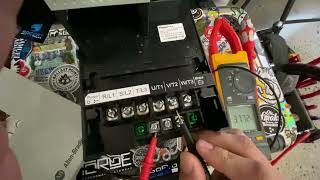
Fixing it starts with finding the root cause. If it's an electrical supply issue, first check your input voltages. L1 to L2, L1 to L3, and L2 to L3 with a voltmeter.
Make sure they're balanced and within the manufacturer's recommended range. If the drive trips even when idle, a high delta power source could be the reason. Using a deltay isolation transformer can help.
If voltages are correct, but the DC bus is still high, harmonics may be the problem. In which case, installing RFI filters upstream can help smooth things out. For situations where line voltage is simply too high, a buck boost transformer in buck mode can bring it back down.
Now, if the overvoltage fault only happens when you slow the motor down, that's a clear sign of mechanical inertia causing regeneration. In simple terms, the load is driving the motor like a generator, pushing energy back into the drive. To deal with that, you can increase the deceleration time in the VFD so the motor slows down more gradually, giving the system time to safely dissipate energy.
If you can't afford a slow stop, add a dynamic braking resistor or brake chopper to absorb the excess energy. For very high inertia loads, you might even need a mechanical brake, like a friction brake, for extra stopping power. By systematically checking the power supply, harmonics, braking systems, and deceleration settings, you can not only eliminate DC bus overvoltage faults, but also extend the life of your VFD and keep your equipment running reliably.
Okay, moving next to the most common reason for motor overheating. I am just summarizing this before moving into VFD parameterization. Once a perfectly good motor burned out.
In most cases, it's just because the ventilation path was blocked which lead to heat built up and as a consequence the motor burnt. I also observed the ambient temperature crossed 40°. But no one added extra cooling like cooling fan.
The insulation didn't stand longer then. Moreover, I've also observed the motors overheat simply because the duty cycle didn't match the load. Another factor is the overcurren.
That's the silent killer caused by overload imbalance or wrong VFD settings. And in high altitude sites, thin air robbed motors of cooling power. Worst of all is an unders sized motor running at full load every day.
If you are interested in more VFD and motor faults and issue, drop the text and comment. I'll make a bonus video for you. What I explained here is real practical experience that you get benefit of it.
Your support on this video will be a token of appreciation for me. Okay, moving to VFD parameters. I am scrolling for each menu, but you have to be specific for your VFD and motor rating.
It could vary motor to motor and VFD to VFD. Before you change anything on a Danfos VFD, take a moment to slow down and go through each parameter in detail. The keypad makes it easy to scroll and adjust values, but that also means mistakes can happen just as easily.
Always start by reviewing the parameter list. Understand what each setting controls from motor data and ramp times to limits, control modes, and safety features. Don't rely on memory alone.
Verify values against the data sheet, motor name plate, and application requirements. Pay special attention to parameters that impact protection, such as current limits, and fault handling. Even a small change in acceleration time, frequency limit, or control mode, can affect motor performance and system stability.
So, double check before you press enter. One wrong setting could cause overheating, nuisance trips, or even equipment damage. Remember, careful parameter review isn't wasted time.
It's the best insurance for a reliable, safe, and efficient VFD operation. I believe you've watched this video till the end, and I hope it will make a real difference in how you handle VFD related issues. Thank you for watching my video.
Don't forget to like, subscribe, and sharing this technical video.