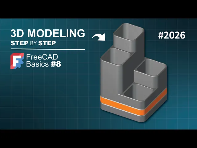
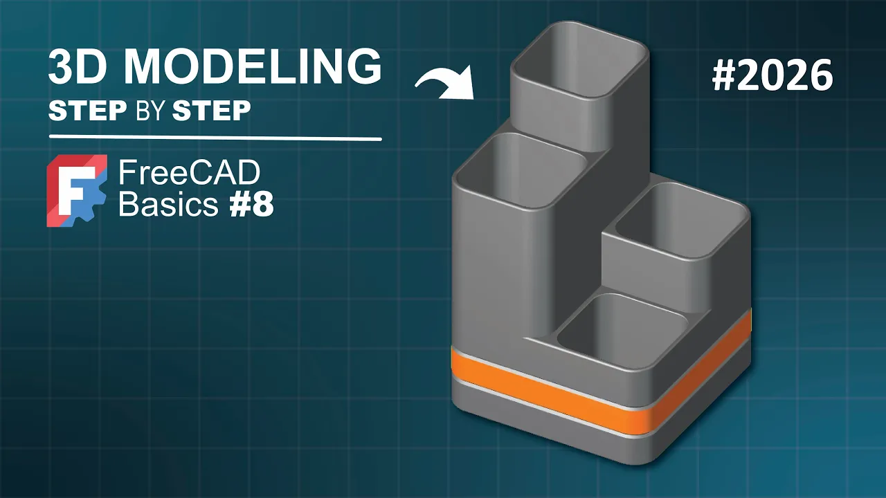
This free the model might look a bit complex, but the truth is that it is very simple to model in FreeCAD. In this video, I will show you how you can design a model like this using the Part Design workbench step-by-step. You can start by creating a document based on the Part Design workbench using the parametric body option to create a new document.
Here we have the body object and with this body object, we can start by creating a sketch attached on the XY plane of this body object. To do that, we go to the Part Design helper features this toolbar and we click on new sketch command icon and we select the XY plane. Just click on this plane.
And here we have our first sketch. We're on the Sketcher workbench and the idea on this sketch is to create a rectangular geometry. To do that, we can go to the Sketcher geometry stool bar, these all tools here and then expand rectangle tools and select centered rectangle and now we click on the start point of this sketch and for this demonstration, we will be using random dimensions.
So we can say 108 mm for this distance and the same here. Let's go to our sketch and let's say 108 mm by 108 mm and then enter. And now what you need to do is to zoom out and here we have our geometry.
As you can see, this sketch is fully constrained. If I escape this tool, as you can see, we have fully constrained a sketch here and then we can close this. Just press this button.
And now press home on the keyboard to center the sketch on the 3D view. And now that we have created the sketch, we can select it here on the tree view and then click on this icon, the pad icon, to extrude the sketch. We can say 90 mm for this extrusion.
We go to the pad parameters. We go to length, and we change here to 90 mm, and then we click off. And this is the preview, and now we can press okay to finish the pad parameters, and here we have our first shape for the 3D model.
The next thing that we can do here is to create another sketch, and we'll use that sketch to create these all extrusions. So, okay. Let's go to part design helper features toolbar, and click on new sketch command icon, and let's select the XY plane as the attachment plane of this sketch.
Let's switch to the section view, click on this icon, and now we can see the axis cross here on this sketch. The next thing that we'll do is to create a rectangular geometry, and to do that we can go to the sketcher geometry toolbar, expand rectangle tools, and now let's select rectangle because we're going to start this geometry here on the region, and click off. And now let's select the dimension tool from sketcher constraints toolbar.
Let's click on this line here, click off, 90 mm, and the height will be the same dimension, 90 mm, and now we have a fully constrained sketch, as you can see. Let's close it by pressing this button. Okay.
As you can see here, we have the 3D model, and the sketch that we created is here on the bottom face of this box, this 3D model. The idea here is to change the attachment of this sketch 001 to this face here of this box. To do that it's very easy.
We need to go to the tree view and the body object. Inside the body object, let's select the sketch 001. One click.
And now right click on mouse and now we have these all options. The option that we need to use is this one here, attachment editor. Click on this option and now as you can see we have a new task panel here.
What I have to change is this plane here. So click on this plane button and now let's select the base face. You can refresh the document to see if we have problems on the attachment and we don't have problems.
So we can press okay and now we can use the sketch here to create an extrusion. We can create the this extrusion here. So let's go to our document.
Let's select the sketch 001 and now let's use this tool here, pad feature, to extrude this sketch. And pad parameters we go to the length parameter and we change it to 120 mm like this. And then we can click off and then okay and you will have the extrusion.
And now to create these other extrusions, what we're going to do is to What we're going to do is to reuse the sketch that we used it for this extrusion and to do that we can go to the tree view, expand the tree of the last feature, this pad 001 and then select the sketch 001 here, control C and on this window, this small window, let's click on user original selection and now let's press control V on Windows to paste the sketch on the same document. Now let's select the sketch and hit space bar to make it visible. As you can see, we have the sketch here.
Now, let's drag the sketch into the body object and the next let's change the attachment of this of this sketch 002. With the sketch selected, right click on mouse and click on attachment editor. Now, this time we can add the second reference.
To do that, we go to the task panel in attachment we can begin reference two and I think we can select this vertex. >> [snorts] >> As you can see, we have this. The next thing that we can do here is to go to attachment offset and as you can see, here we have the Z axis on this duration and this is the duration that we'll change in order to attach this sketch here on this face.
So, let's go to around the axis and let's say, for example, 90° and see what happens and as you can see, we have this. Let's change the value to 180° and then click off and now as you can see, we have this. Let's press okay.
And next, let's select the sketch 002 and use the pad tool to extrude the sketch. Okay, for this extrusion, let's say 50 mm. Let's go to the length parameter in the pad parameters and type 50 mm and then click off and now let's [clears throat] press okay.
For this extrusion here, we can just select this face here and extrude it using the pad feature. We don't need to pass another sketch and change its attachment. We don't need that.
So, we can select this face here and then click in pad feature and [clears throat] here we have the extrusion. The next thing that we need to do is to change the length of this extrusion in the pad parameters. Let's go to length parameter and let's change it to 107 mm and then hit okay.
Now press home on the keyboard and here we'll have the extrusions. The next thing that we can do is to add this fillet feature here. To do that we can start by selecting this edge here of the freedom model and then go to part and there's a features toolbar.
There's all tools here and click in fillet feature command icon. And here we can change the radius to 20 mm select and now let's select all edges that we need on this fillet feature. So let's select this edge.
This one here, this edge and this, this edge and this one here and next this edge. And now let's rotate the view and then this edge and okay to confirm. And here we have this.
The next thing that we can do here is to create a these pockets here as you can see. To do this it's very very simple. Let's go to our document.
Let's select this top face here and create a sketch on this top face here. To do that it's very simple. We have the face selected, we click on this sketch command icon and a sketch will be created and it will be automatically attached to this face here.
The next thing that we need to do is to import the edge of this face here. We need to change the geometries to construction geometries. To do that we click on this icon and as you can see now we have this behavior.
And next, let's go to Sketcher Tools and let's use this tool here, external projection tool. Let's click on this face here, and now we have this, as you can see. Now, it's time to escape this tool, the external projection geometry tool.
Right click, change the geometries to normal mode. Click on this icon to do that. And next, select the imported geometries in this way, and go to Sketcher Tools toolbar, and click on this icon, offset.
And now, we need to add a constraint for this offset here. To do that, we go to the task panel, go to offset parameters, and check eight offset constraint. And here, we will set minus 4 mm, and then enter.
And here, we have an offset of the imported geometries. As you can see, this geometry here is fully constrained, and this geometry will appear on the pocket feature. The next thing that we can do is to create the mirror of this geometry.
To do that, it's very easy. Double click on this edge, for example, and as you can see, the entire geometry is selected. And the next, go to Sketcher Tools of Sketcher Workbench, and click on mirror, this tool, and check this option, create symmetric constraints.
And now, just click on the vertical axis. And now, double click on this edge, and do the same here. And as you can see, these two geometries are selected.
Click on mirror, create symmetric constraints, and now click on the horizontal axis. And here, we have a fully constrained sketch. Press close button.
And now, let's use the pocket feature to create a pocket. Okay, as you can see on the pocket parameters, we have a length of 5 mm for this pocket feature. And this is not what we want.
The thickness here of this model is 4 mm. So So the idea here is to get the same thickness on on the bottom face of this model. Let's go to the type parameter.
Click on it and let's select up to face. And next, rotate the view and select this bottom face. Okay, and now the next thing that we can do, let's change to front view.
And as you can see here, if we if we for example press okay, as you can see the result is this and this is not what we want. So, double click on the pocket feature. And what you need to do here is to add an offset from this face here and to do that it's very easy.
We need to go to offset to face parameter and say minus 4 mm. Now if we change to front view, as you can see we have this face here. Let's press okay.
Press home on the keyboard and the next thing that we can do here is to add these small fillets here and after that we will create a these pocket here. Okay, let's do that. Let's start by selecting this edge and go to fillet feature command icon.
Let's change the radius to something like 2 mm. Click on select button and select this edge, this edge and this bottom edge here and next this edge. And okay.
Okay, here we have this. What is missing now is another fillet feature. Let's select this internal edge here and go to the fillet feature command icon and set the radius of 1 mm and then click on select button.
And let's select this edge, this edge, and this one here and then press okay. And it's all. What is missing to do now is to create at this pocket here.
To do that, it's very simple. We will need a sketch on the XY plane of the body object. Let's click on new sketch command icon and select XY plane as the attachment plane.
Let's [snorts] change to section view to see the axis crossing. Click on this icon and the next thing that we can do here is to import this edge here into our sketch as a reference geometry. First, we need to change the geometry to construction and geometries.
Click on this icon to do that. And next, let's use the external projection geometry and import this edge here as a reference. Okay.
Next, let's change the geometry to normal mode and let's select the polyline tool and let's create the geometry here. Let's create at this triangle this way. Escape the tool, right click, and now let's choose the perpendicular constraint to make these two lines here perpendicular.
As you can see, we have 3 degrees of freedom. Next, let's escape this tool and let's drop this point to here. Okay.
For these two lines here, this line and this one here, select the two lines, let's apply an equal constraint. To do that, we go to sketch constraints and then we click on this icon and here we have this. Two degrees of freedom left.
Let's Let's drag this point a little bit. And okay, we have a thickness of 4 mm here for this wall. So, from this line here to this point, we can set a distance of 2 mm.
Select dimension tool, click on this point, and now on this imported edge, click off, and let's say 2 mm, and then enter. Next, before we full constrain the sketch, let's create a copy of this geometry. Sketch this tool, select this geometry, and press control plus C, and now control plus V, and here we have five degrees of freedom.
Now, let's drag this Let's drag this Let's drag this geometry. As you can see, we have this. Now, if we drag this geometry Now, if we drag this point, as you can see, this geometry here is not constrained.
So, the first thing that we can do is to select the base line here, and make it a vertical line. Expand the tools here, and select vertical constraint, and now select this point and this imported edge, and let's place a coincident constraint. And next, let's select that this line here and this one here, and make them equal.
We have two degrees of freedom, as you can see. Next, we can use the dimension tool to set the distance between this point here to the horizontal axis. Let's say 26 mm, and next, let's move this geometry to this position.
And let's select the dimension tool again, and now from this point to this point here of this geometry, let's say 22 mm, and then okay. We have a fully constrained sketch. Let's close it.
And next, we have to remove material from this freedom model. And to do that, we're going to use the subtractive tools of part design workbench, these tools here. We will use this tool here, subtractive pipe.
Okay, so this means that this sketch here that we created, we will use it as a profile. And the edges of this freedom model, we will use that we will use them as path. So, with this sketch 004 selected, let's click on subtractive pipe command icon.
Press on on the keyboard, and as you can see on the 3D view, we only see the sketch with these two geometries. What you need to do is to make the freedom model visible. To do that, we go to the tree view, and we make and we make this fillet 002 visible.
Click on this icon, or you can select the fillet 002, and then press spacebar. Okay. Now, let's rotate the view like this.
And let's go to the pipe parameters. And what you need to do here is to add this bottom edge here of this freedom model as path to our profile sketch. So, click on this button, add edge, and let's add this edge.
Okay, as you can see, we have this preview here. Click again on this button, and add this all edges. Okay, now we have this.
What you need to do is to press okay and this is the final shape of the freedom model. So, this was a demonstration. Thank you for watching this video.
If you find this video useful, please don't forget to hit like and share this video with your friends.