hello and welcome to my next tutorial about prepo mix this time i will show you how to use remote load to analyze the shaft subjected to combined loading as always let's create a new model first i will use the unit system of my meters and now i can import the geometry using step file format the geometry is already imported so i can create the mesh i will specify meshing parameters and this will be 20 millimeters for maximum element size i can use the preview option confirm this and generate the mesh the mesh is now generated
so let's proceed to another setup i can define material first this will be steel material just like in previous tutorials and i will specify the same elastic properties young's modulus and poisson's ratio for this material now i can create a section this will this will be applied to the whole shaft and with proper material selected and now i could proceed to the step setup create a new step define step related features such as boundary conditions and loads but i'll create a reference point and rich body constraint first because in one of the previous videos i
told you that rigid body constraints have several applications they can be used to apply torque to solid models or they can be used to create rigid parts or remote loads and that's what we'll do today let's create a new reference point first uh i have to specify coordinates first of all i will define offset in the z-axis and so that the point goes from this end to the other one and i will also have to specify offset in x-axis so that the point is actually at a remote location from this face right here let's confirm
this and now i can create the rigid body constraint and this reference point will be automatically selected i just have to pick a face and so this face right here i can confirm this and now we have a rigid body constraint defined and you can see the symbols of this constraint and how the reload will be transferred using this constraint from this point to this phase let's create a new step now this will be static step with default settings i can confirm this and now i'll create a boundary condition and this shaft is supposed to
be fixed at one end because it's a form of cantilever so let's define a fixed boundary condition at this end and i also have to specify load this will be concentrated first i will choose the reference point that we defined and the load will be acting in y direction and the value is eight kilo newtons so that's the the load magnitude here i can confirm this and now you can see how the load acts with respect to this phase this will cause both torsion and bending of the shaft i can submit the analysis now and
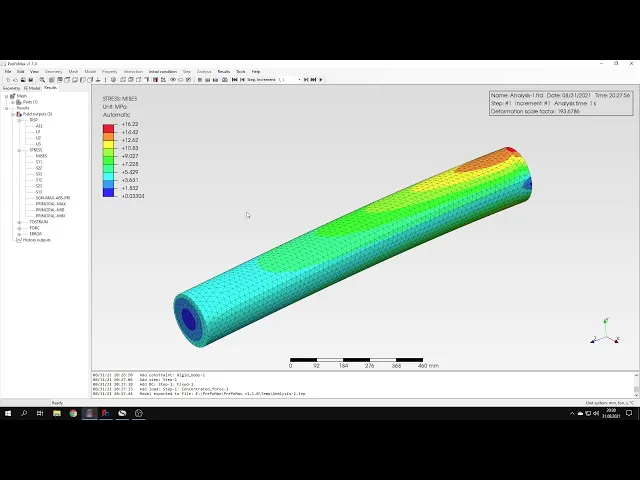
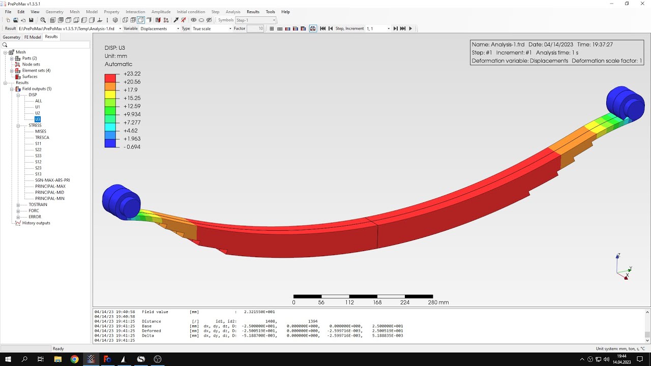
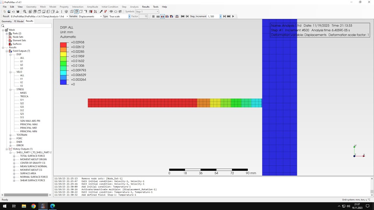
it shouldn't take long because the mesh is not so dense the results are already available so let's check them here you can see the deformation but we are interested mainly in the stresses so i'll select the full misses stress plot but first of all let's take a look at the deformation of this model uh i could i will choose a different view let's make sure that we have a proper setting for for deformation factor i could use automatic one true scale turn it off or you specify my amount value of the deformation factor but i
will stay with the automatic one and now i can use animation and to see how this how the shaft actually deforms you be able to see a torsion very well here mainly bending and that's because of the specific of this section for rectangular section you would see actual actual torsion but on the other hand rectangular section will be much more difficult to evaluate in terms of stresses due to stress concentrations in the corners so i decided to use circular section but using this animation you should be able how the shaft deforms that you may even
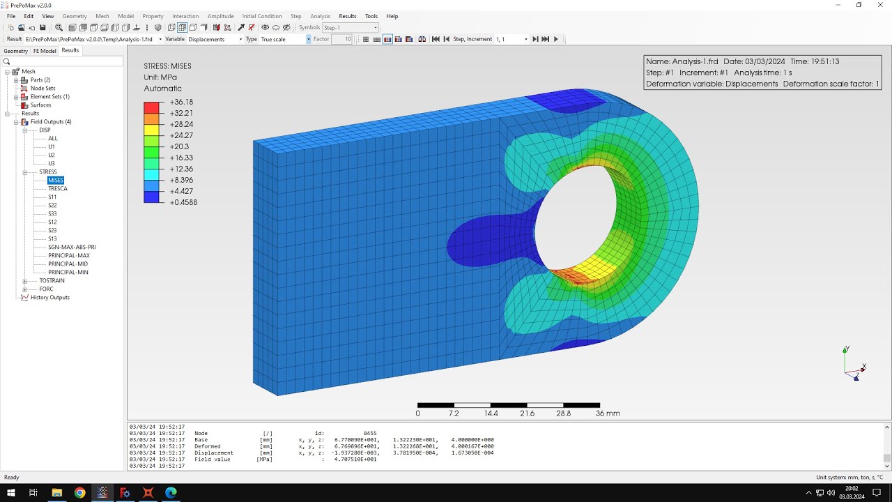
notice some torsion here because it definitely occurs so let's here are the some animation settings you can specify number of frames per second and other options for the animation let's close this and stop the animation now let's check the stresses according to analytical solution i'll use the query tool um to check the stress at different locations and here's the analytical solution for bending torsion and combined loading that's the phone is stress that we expect to have in this model so let's see how it looks like in the model and let's check some locations for the
stress and you can see that the values of the stress are very close to what we got from the identical solution especially here and you can notice there's a very good agreement with analytical solution and so we can say that the analysis were performed correctly of course we could use finer mesh to get even better results but for now this should be enough and so so that's it for for this paperback tutorial thank you very much for your attention as always feel free to ask any questions and suggest topics for future tutorials in the comments
have a nice day and see you in the next video